CTPSTS
Bulk Data Entry Plane stress triangular element connection. Defines a plane stress triangular element in the x-z or x-y plane.
Format
| (1) | (2) | (3) | (4) | (5) | (6) | (7) | (8) | (9) | (10) |
|---|---|---|---|---|---|---|---|---|---|
| CTPSTS | EID | PID | G1 | G2 | G3 | G4 | G5 | G6 | |
| Theta |
Example
| (1) | (2) | (3) | (4) | (5) | (6) | (7) | (8) | (9) | (10) |
|---|---|---|---|---|---|---|---|---|---|
| CTPSTS | 111 | 2 | 31 | 74 | 75 | 32 | 51 | 52 | |
| 15.0 |
Definitions
| Field | Contents | SI Unit Example |
|---|---|---|
| EID | Unique element
identification number. No default (Integer > 0) |
|
| PID | A PPLANE entry identification
number. Default = EID (Integer > 0) |
|
| G1, G2, G3 | Identification numbers
of connected corner grid points. These fields are mandatory. No default (Integers > 0, all unique) |
|
| G4, G5, G6 | Identification numbers
of connected edge grid points. No default (Integers > 0 or blank) |
|
| Theta | Material orientation angle in
degrees. Default = 0.0 (Real) |
Comments
- Element identification numbers must be unique with respect to all other element identification numbers.
- The Grid ordering of
G1 through G6 is defined as:
Figure 1. 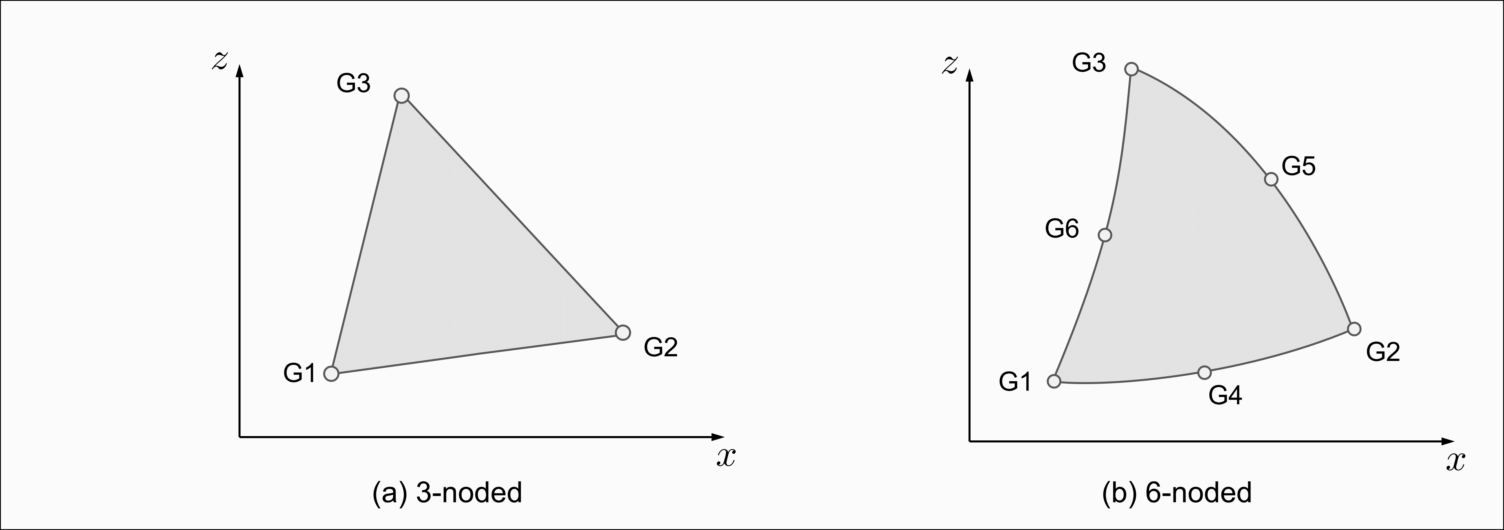
- The continuation is optional.
- The definition of the elemental coordinate system and material orientation angle theta is the same as defined for CTRIA3 and CTRIA6, depending on the number of nodes of CTPSTS elements.
- Plane stress analysis defined in x-y plane is supported, that is. the axis labels of “z” can be replaced by “y”. The out-of-plane normal direction defined by the corner node sequence with the right hand rule should point to the z direction if the element is in the x-y plane, or the -y direction if in the x-z plane.
- A concentrated load (for example,
a load specified by a FORCE entry) at a grid Gi of this
element is defined to distribute along the thickness, T, of the element. For
example, to apply a load of 200 N/m to a node Gi with the element thickness
being 0.05 m, the amount to be specified on the load entry should be
(200N/m) * 0.05m = 10N.
The default thickness of 1.0 is used if T is not specified on the PPLANE entry.
- Plane stress elements are
supported in:
- Linear static analysis
- Nonlinear Static analysis (Small and large displacement)
- Linear Transient Analysis
- Frequency Response Analysis
- Real and Complex Eigenvalue Analysis
These elements are currently not supported in:- Inertia Relief analysis
- Buckling analysis
- Heat transfer analysis
- Optimization
- For plane stress elements, stress and strain are output by default in the material coordinate system defined by theta. PARAM,OPSTS,OLD can be used to output stress and strain in the elemental system for H3D format. If PARAM,OPSTS,OLD is set, PARAM,OMID,NO can be used to output stress and strain in the elemental system for OPTI format. PARAM,OMID,NO is automatically changed to PARAM,OMID,YES if PARAM,OPSTS,NEW is used. PARAM,OPSTS,NEW is the default option, which dictates that the stress and strain of plane stress elements be output in the material system.
- Currently only the DIRECT type of stress and strain results are output for plane stress elements in the material coordinate system in H3D format.