Category: Toolbox > eDrives > Motors
Inputs:
•U_s: Input voltage vector for motor in alpha-beta convention.
•T_l: Load torque.
•Rotor_lock: Clamp enable for motor shaft. When input is set to 1, the shaft speed is forced to zero. (binary input)
Outputs:
•psi_R: Rotor Flux vectors in d-q axes coordinates.
•i_s: Output current vector for stator currents in alpha-beta coordinates.
•T_me: Mechanical shaft torque of the motor.
•w_me: Mechanical shaft speed of the rotor.
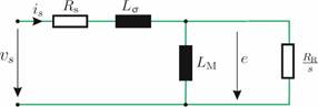
Description: The Induction Motor-IRTF block is a motor model for a three phase AC Induction machine. This is a mathematical model of an electrical machine based on the Ideal Rotating Transformer model. A four parameter model representation, as shown below, is used.

Leakage Inductance (H): Indicates the combined (stator/rotor) stator referred leakage inductance.
Magnetizing Inductance (H): Indicates the stator
referred magnetizing inductance  .
.
Number of Pole Pairs: Indicates the number of motor pole pairs.
Rotational Inertia: Indicates the inertia of the rotor (plus mechanical load if attached).
Rotor Resistance (ohms): Indicates the stator
referred rotor resistance  .
.
Stator Resistance (ohms): Indicates the stator
winding resistance  .
.
Slip (shown in the equivalent model above): Defined as  where
where  represent the synchronous and
mechanical shaft speed, respectively.
represent the synchronous and
mechanical shaft speed, respectively.