
Creating Symmetry Planes
Create a symmetrical die by reflecting a part across a symmetry plane.
-
On the Die Design ribbon, select the Symmetry
tool.

-
Select the Symmetry tool.
Tip: To find and open a tool, press Ctrl+F. For more information, see Find and Search for Tools.The Die Symmetry guide panel is displayed.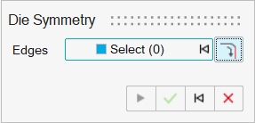
-
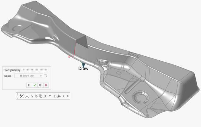
Use the Edges collector to select the edges you want to
use to define the symmetry plane.
The selected edge must be on a plane and the plane must be orthogonal to the draw direction if the draw direction is defined. A preview of the symmetry plane is displayed if the selection is valid.Tip: Selecting a midpoint as a symmetry plane allows you to cut the part in half along that plane. For example, the symmetry plane in the following image is used to cut the channel in half:
-
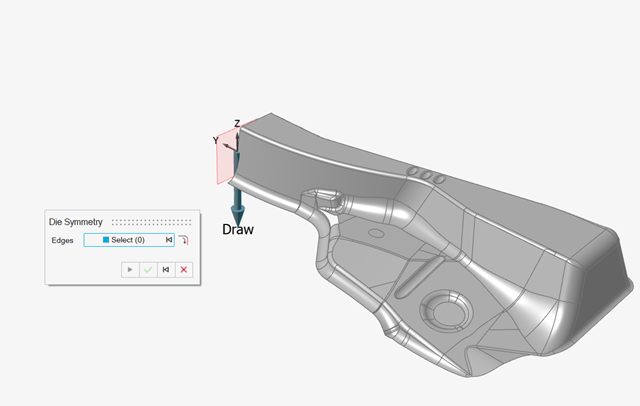
You can use the microdialog to adjust the symmetry plane, orientation, or
alignment; reset the direction; or apply symmetry:

Option Description 
Select which half of the symmetry plane to keep. 
Use the Move tool to move the symmetry plane. 
Orient the symmetry plane by clicking to define two points.
Orient the symmetry plane by clicking to define three points. 
Align the symmetry plane to the reference plane. X Y Z Align the symmetry plane to the system X, Y, or Z axis. 
Reset the direction of the symmetry plane. 
Apply symmetry. - Right-click and mouse through the check mark to exit, or double-right-click.