Define Hotspots
Define a nodal hotspot to assign crack properties.
-
Click the Hotspot tool.
Figure 1.  The Hotspot guide bar opens.
Figure 2.  The hotspot guide bar contains the following options:
- Type of Hotspot creation: Manual (default) and configuration file input.
- Node selection for manual hotspot creation.
- Create Hotspot after node selection.
- Crack properties at hotspot.
-
Click the sandwich icon to open the Hotspot creation options.
Figure 3.  Creation option is set to Manual by default.
Figure 4. 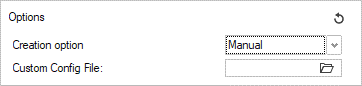 Custom Config file allows the user to:
- Create a hotspot at the required node.
- Create-assign a system to define the crack direction.
The feature requires a configuration file (.txt) linked to a .csv file containing nodal information for system creation using three nodes.
Configuration file:Figure 5. 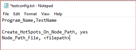 Nodal Path file (.csv)
Figure 6. 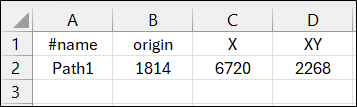
<Path Name>, <Origin node ID>, <Crack Direction node
                            ID / end node ID defining thickness along crack length>, <Stress
                            Distribution plane node ID>
Header information is necessary to define the Stress distribution plane XY/XZ during system creation. The crack direction will always be set to X. If no header is defined in the nodepath file, the system created will always be in X direction and default plane chosen is XZ.
If
Create_HotSpots_on_Node_Path = Yes, hotspot is created at the origin node and listed in Hotspot dialog. -
Click the sandwich with dropdown icon to define crack definition options.
Figure 7. 
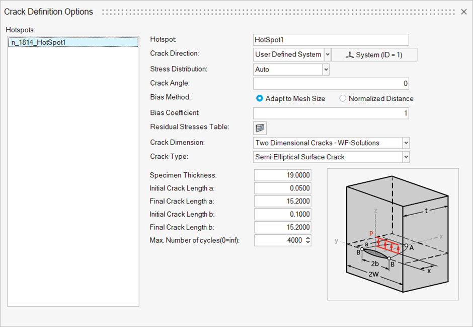
- Crack Direction:
- Normal: Surface normal at the selected node across the thickness.
- System: User-defined system defining crack direction and crack plane.
- Stress Distribution: stress distribution calculated along the crack
direction. Options:
- Auto: stress in the XZ plane as per the default system (Default)
- Absolute Maximum Principal: Absolute max. principal stress in the XZ plane along the crack direction
- YY: stress in the XY plane of the defined system
- ZZ: stress in the XZ plane of the defined system
- Crack Angle: rotation of the stress distribution plane about X-axis (crack direction)
- Biasing Options:
-
Adapt to Mesh Size: Creates query points across the model thickness along the crack direction considering mesh size.
Bias Coefficient (0 < value <= 1.0)
Along the crack direction, distance between two consecutive stress evaluation points in a mesh is determined by the bias coefficient x minimum distance between centroid and corners.
- Normalized Distance: User-defined normalized distance (0 to
1) file with required biasing along the crack direction.
Figure 8. 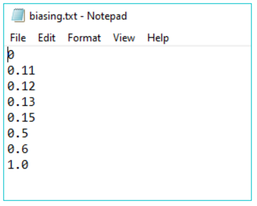
-
- Residual table defines the residual stress defined to the
hotspot.Import residual stress file in .txt format per hotspot.
Figure 9. 
- Crack dimension supported are:
- 1D Dimensional Crack – WF solutions
- 2D Dimensional Crack – WF solutions
- Crack types supported are listed in Chapter: Shows Crack Types.
- The crack dimension vary based on the crack type selected.
- Crack Direction: