/BEAM
Block Format Keyword Describes beam elements. Two properties (/PROP/TYPE3 (BEAM) and /PROP/TYPE18 (INT_BEAM)) are available for beam elements. The properties describing a beam element are all defined in a local beam coordinate system.
Format
| (1) | (2) | (3) | (4) | (5) | (6) | (7) | (8) | (9) | (10) |
|---|---|---|---|---|---|---|---|---|---|
| /BEAM/part_ID | |||||||||
| beam_ID | node_ID1 | node_ID2 | node_ID3 | VX | VY | VZ | |||
Definition
| Field | Contents | SI Units Example |
|---|---|---|
| part_ID | Part identifier of the
block. (Integer, maximum 10 digits) |
|
| beam_ID | Element
identifier. (Integer) |
|
| node_ID1 | Node identifier
1. (Integer) |
|
| node_ID2 | Node identifier
2. (Integer) |
|
| node_ID3 | (Optional) Node identifier
3. (Integer) |
|
| VX | X component of the orientation vector to defined plane
XY. (Real) |
|
| VY | Y component of the orientation vector to defined plane
XY. (Real) |
|
| VZ | Z component of the orientation vector to defined plane
XY. (Real) |
Comments
- The identifier (ID) must be unique in each element family, but it is advised for each element type to have a unique element identifier in the global model.
- More than one beam block may be used to define a part.
- Any number of beams may be defined in one block.
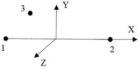
- The initial local coordinate system of
beam:
node_ID1 and node_ID2 define local X-axis.
The local plane XY is defined with:- the vector (VX, VY, VZ).
- the node node_ID3 if vector (VX, VY, VZ) are not defined.
- the global Y axis (or the global Z axis in cases where node_ID1 and node_ID2 are along global Y axis) if node_ID3 and vector (VX, VY, VZ) are not defined.
Local Z axis is orthogonal to the XY plane.
Local Y axis is the vector product of local Z and local X.Figure 1.