
/PROP/TYPE6 (SOL_ORTH)
Block Format Keyword Describes the orthotropic solid property set. This property set is used to define the fiber plane for /MAT/LAW14(COMPS0), the steel reinforcement direction for /MAT/LAW24 (CONC) or the cell direction for /MAT/LAW28 (HONEYCOMB).
This property is only available for 8-node linear solid elements (/BRICK), tetrahedron elements (/TETRA4 and /TETRA10), and 2D solid elements (/QUAD). Quadratic bricks (/BRIC20 and /SHEL16) and pentahedron elements (/PENTA6) are not compatible with this property.
Format
| (1) | (2) | (3) | (4) | (5) | (6) | (7) | (8) | (9) | (10) |
|---|---|---|---|---|---|---|---|---|---|
| /PROP/TYPE6/prop_ID/unit_ID or /PROP/SOL_ORTH/prop_ID/unit_ID | |||||||||
| prop_title | |||||||||
| Isolid | Ismstr | Icpre | Itetra10 | Inpts | Itetra4 | Iframe | dn | ||
| qa | qb | h | |||||||
| Vx | Vy | Vz | skew_ID | Ip | Iorth | ||||
| Px | Py | Pz | |||||||
| Vdef_min | Vdef_max | APS_max | COL_min | ||||||
| Ndir | sphpart_ID | Icontrol | |||||||
Definition
| Field | Contents | SI Unit Example |
|---|---|---|
| prop_ID | Property
identifier. (Integer, maximum 10 digits) |
|
| unit_ID | Unit identifier. (Integer, maximum 10 digits) |
|
| prop_title | Property
title. (Character, maximum 100 characters) |
|
| Isolid | Solid elements formulation
flag. For TETRA4 and TETRA10 only Isolid
=1 is available.
(Integer) |
|
| Ismstr | Small strain formulation
flag. 3
(Integer) |
|
| Icpre | Constant pressure
formulation flag. 4 Only valid when Isolid = 14, 17, 18 or 24.
(Integer) |
|
| Itetra10 | 10 node tetrahedral
element formulation flag. 12
(Real) |
|
| Inpts | Number of integration
points (only for Isolid
=14). (Integer) = ijk (Default = 222): 2 < i,j,k < 9 for Isolid =14. Where:
|
|
| Itetra4 | 4 node tetrahedral element
formulation flag. 12
(Real) |
|
| Iframe | Element coordinate system
formulation flag (only for quad and standard and compatible 8-node
bricks: Isolid =
1, 2, or 17,
Isolid = 14 or 24 always use the
co-rotational formulation.
(Integer) |
|
| dn | Numerical damping for
stabilization. Only valid if Isolid =24. Default = 0.1 (Real) |
|
| qa | Quadratic bulk
viscosity. Default = 1.10 (Real) Default = 0.0 for /MAT/LAW70 |
|
| qb | Linear bulk
viscosity. Default = 0.05 (Real) Default = 0.0 for /MAT/LAW70 |
|
| h | Hourglass viscosity
coefficient. Only valid if Isolid =1 or 2. Default = 0.10 (Real) must be 0.0 < h < 0.15 |
|
| Vx | X component for reference
vector. 9 (Real) |
|
| Vy | Y component for reference
vector. 9 (Real) |
|
| Vz | Z component for reference
vector. 9 (Real) |
|
| skew_ID | Skew frame identifier
defining orthotropic directions. (Integer) |
|
| Ip | Reference plane. 9
(Integer) |
|
| Iorth | Orthotropic system
formulation flag.
(Integer) |
|
| Orthotropic angle with
first reference plane direction. 9 Only used with Ip > 0. (Real) |
||
| Px | X coordinate of reference point P (used only with Ip = 21 or 24). | |
| Py | Y coordinate of reference point P (used only with Ip = 21 or 24). | |
| Pz | Z coordinate of reference point P (used only with Ip = 21 or 24). | |
| Minimum time step for
solid elements. Only available when using /DT/BRICK/CST or /DT/BRICK/DEL. Default = 0.0 (Real) |
||
| Vdef_min | Minimum volume ratio
(V/Vo) to delete solid element. If Ndir ≥
1, the element is deleted and SPH elements are
activated. Default = 0 |
|
| Vdef_max | Maximum volume ratio
(V/Vo) to delete solid element. If Ndir ≥
1, the element is deleted and SPH elements are
activated. Used only if different from 0. Default = 0 |
|
| ASP_max | Maximum aspect ratio to
delete solid element. If Ndir ≥
1, the element is deleted and SPH elements are
activated. Used only if different from 0. Default = 0 |
|
| COL_min | Minimum collapse value to
delete solid element. If Ndir ≥
1, the element is deleted and SPH elements are
activated. Default = 0 |
|
| Ndir | Number of
particle/direction for each solid element.
(Integer) |
|
| sphpart_ID | Part identifier describing
the SPH properties for Sol2SPH. (Integer) |
|
| Icontrol | Element distortion control flag.
(Integer) |
Example 1
#RADIOSS STARTER
#---1----|----2----|----3----|----4----|----5----|----6----|----7----|----8----|----9----|---10----|
#-  1. LOCAL_UNIT_SYSTEM:
#---1----|----2----|----3----|----4----|----5----|----6----|----7----|----8----|----9----|---10----|
/UNIT/2
unit for prop
#              MUNIT               LUNIT               TUNIT
                  kg                  mm                  ms
#---1----|----2----|----3----|----4----|----5----|----6----|----7----|----8----|----9----|---10----|
/SKEW/FIX/1
New SKEW 1
#                 OX                  OY                  OZ
                   0                 100                   0
#                 X1                  Y1                  Z1
                   1                   0                  -1
#                 X2                  Y2                  Z2
                   0                   1                   0
#---1----|----2----|----3----|----4----|----5----|----6----|----7----|----8----|----9----|---10----|
#-  2. GEOMETRICAL SETS:
#---1----|----2----|----3----|----4----|----5----|----6----|----7----|----8----|----9----|---10----|
/PROP/SOL_ORTH/1/2
SOL_ORTH example
#   Isolid    Ismstr               Icpre  Itetra10     Inpts   Itetra4    Iframe                  dn
        14        -1                  -1         0         0         0        -1                   0
#                q_a                 q_b                   h
                   0                   0                   0
#                 Vx                  Vy                  Vz   skew_ID        Ip     Iorth
                   0                   0                   0         1         0         0
#                phi                  Px                  Py                  Pz
                   0                   0                   0                   0
#         deltaT_min            vdef_min            vdef_max             ASP_max             COL_min
                   0                   0                   0                   0                   0
#     Ndir sphpartID  Icontrol
         0         0         0
#---1----|----2----|----3----|----4----|----5----|----6----|----7----|----8----|----9----|---10----|
#enddata
#---1----|----2----|----3----|----4----|----5----|----6----|----7----|----8----|----9----|---10----|
Example 2
#RADIOSS STARTER
#---1----|----2----|----3----|----4----|----5----|----6----|----7----|----8----|----9----|---10----|
#-  1. LOCAL_UNIT_SYSTEM:
#---1----|----2----|----3----|----4----|----5----|----6----|----7----|----8----|----9----|---10----|
/UNIT/2
unit for prop
#              MUNIT               LUNIT               TUNIT
                  kg                  mm                  ms
#---1----|----2----|----3----|----4----|----5----|----6----|----7----|----8----|----9----|---10----|
/PROP/SOL_ORTH/1/2
SOL_ORTH example
#   Isolid    Ismstr               Icpre  Itetra10     Inpts   Itetra4    Iframe                  dn
        14        -1                  -1         0         0         0        -1                   0
#                q_a                 q_b                   h
                   0                   0                   0
#                 Vx                  Vy                  Vz   skew_ID        Ip     Iorth
                   0                   0                   0         0         1         0
#                phi                  Px                  Py                  Pz
                  45                   0                   0                   0
#             dt_min            vdef_min            vdef_max             ASP_max             COL_min
                   0                   0                   0                   0                   0
#     Ndir sphpartID  Icontrol
         0         0         0
#---1----|----2----|----3----|----4----|----5----|----6----|----7----|----8----|----9----|---10----|
#enddata
#---1----|----2----|----3----|----4----|----5----|----6----|----7----|----8----|----9----|---10----|
Comments
- Isolid - Solid elements formulation
- Isolid =17, brick deviatoric behavior is computed using 8 Gauss points, but the bulk behavior can be chosen with Icpre, and compatible with all solid type material laws.
- Isolid =24 (HEPH) solid elements use a physical hourglass formulation that is similar the hourglass formulation used by Ishell =24 (QEPH) shell elements. This hourglass formulation returns better results than the viscous hourglass formulation used by Isolid = 1 or 2.
- Isolid =14 (HA8) is locking-free general solid formulation. Example: Inpts =222 is an 8 Gauss integration points solid. HA8 formulation is compatible with all orthotropic and isotropic material laws.
- Isolid =18, the Icpre and Ismstr default values
depend on the material and are recommended values:
Default Material Laws Icpre = 2 2, 21, 22, 23, 24, 27, 36, 52, 79, 81, 84 Icpre = 3 12, 14, 15, 25, 28, 50, 53, 68, and If , then 1, 13, 16, 33, 34, 35, 38, 40, 41, 70 and 77
Icpre =1 All other laws and If , then 1, 13, 16, 33, 34, 35, 38, 40, 41, 70, and 77
Ismstr = 10 38, 42, 62, 69, 82, 88, 92, 94, 95 Ismstr = 11 70 Ismstr = 1 28 Ismstr = 2 All other laws
- When using the automatic setting option Ismstr = Icpre = Iframe=-1, the values for these options are defined using the best options based on the element formulation, element type, and material. Alternatively, defining Ismstr = Icpre = Iframe=-2 will overwrite the values for these options defined in this property with the best value (refer to /DEF_SOLID) based on element type and material law. To see the values defined by Radioss, review the “PART ELEMENT/MATERIAL PARAMETER REVIEW” section of the Starter output file.
- Small strain:
- If the small strain option is set (Ismstr=1 or 3), the strains and stresses used in material laws and output to time history and animation result files are engineering strains and stresses. Otherwise, they are true strains and stresses.
- The Radioss Engine option /DT/BRICK/CST will only work for brick property sets with Ismstr =2 and 12.
- The flag Ismstr =10 and 12 are only compatible with material LAW28 which uses total strain formulation.
- Ismstr=12 is compatible with /DT/BRICK/CST, and total strain will be switched to small total strain, but not like the case of Ismstr=2, there is slight discontinuity of stresses during the passage.
- Starting with version 2017, Lagrangian elements whose volume becomes
negative during a simulation will automatically switch strain
formulations to allow the simulation to continue. When this occurs, a
WARNING message will be printed in the Engine output file. The following
options are supported.
Element Type and Formulation Strain Formulation Negative Volume Handling Method /BRICK Isolid=1, 2, 14, 17, 24
/TETRA4
/TETRA10
Full geometric nonlinearities. Ismstr = 2, 4.
Switch to small strain using element shape from cycle before negative volume. Lagrange type total strain . Ismstr = 10, 12.
Lagrange type total strain with element shape at time=0.0.
- Icpre - Constant pressure
formulation flag
- Icpre =1 is used to prevent volumetric locking in incompressible or quasi-incompressible material. For this case, the stress tensor is decomposed into a spherical and deviatoric part. Reduced integration is then used for the spherical part so that the pressure remains constant.
- Icpre =2 is only available for elasto-plastic laws. To prevent volume locking, additional terms with Poisson’s coefficient are added to the strain. When in the material is still elastic and thus compressible, the Poisson’s coefficient terms are small. As the material becomes plastic and thus incompressible, the Poisson’s coefficient terms increase to prevent volume locking. Refer to the Radioss Theory Manual for additional explanation.
- Co-rotational
formulation:
For Isolid =1 or 2, and Iframe =2, the stress tensor is computed in a co-rotational coordinate system. This formulation is more accurate if large rotations are involved, at the expense of higher computation cost. It is recommended in case of elastic or visco-elastic problems with important shear deformations. Co-rotational formulation is compatible with 8 node bricks. Co-rotational formulation is also compatible with bi-dimensional and axisymmetric analysis (/QUAD) element).
- dn - Numerical
damping and h - hourglass viscosity coefficient
- Numerical damping dn is used in the hourglass stress calculation for Isolid=24 (HEPH) solid elements.
- When comparing results between Isolid=24 and Isolid =1 or 2 where dn=h, the numerical damping is times smaller for Isolid =24 than Isolid =1 or 2.
- Output for post-processing
- For post-processing solid element stress, refer to /ANIM/BRICK/TENS for animation and /TH/BRICK for plot files.
- In animation file, if elements are using co-rotational formulation,
- Isolid =14, 24 (co-rotational frame always used)
- Iframe =2 with Isolid =1, 2, 17
Then the stress output is represented in material orthotropic coordinate system defined in /PROP/SOL_ORTH. Otherwise (co-rotational formulation not used), then the stress components (SIGX, SIGY, SIGZ, SIGXY, SIGYZ, and SIGXZ) are expressed in global coordinate system.
- In plot files, the stress components SX, SY, SZ, SXY, SYZ, and SXZ are expressed in the global frame and the stress tensors components LSX, LSY, LSZ, LSXY, LSYZ, and LSXZ are expressed in the orthotropic frame (refer to /TH/BRIC for post-processing solid element stress in plot files).
- Isoparametric systems
(r-s-t)For 8 node bricks (Isolid =1 or 2), 4-node tetrahedron and 10-node tetrahedron, the orthotropic system rotates like the orthogonalized isoparametric system. Attention must be paid to the orientation of the orthotropic system in case of large shear.
Figure 3. 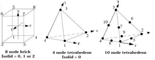
r, s, t: isoparametric frame
r: center of (1, 2, 6, 5) to center of (4, 3, 7, 8)
s: center of (1, 2, 3, 4) to center of (5, 6, 7, 8)
t: center of (1, 4, 8, 5) to center of (2, 3, 7, 6)Figure 4. 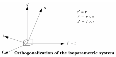
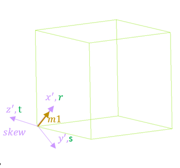
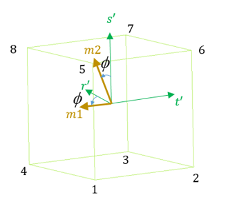
- Orthotropy direction
for 3D solid elements:
Table 1. IP Value Orthotropic Direction IP =0 Orthotropic directions are from the skew_ID directions. If skew_ID is not defined, global coordinate system is used. 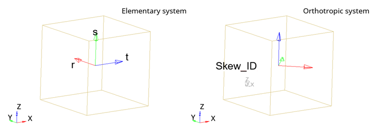
IP =1 The elementary direction t defines the third orthotropic direction. The first and second orthotropic directions are rotated by orthotropic angle in the plane (r,s). 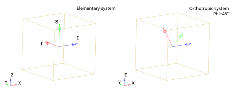
IP =2 The elementary direction r defines the third orthotropic direction. The first and second orthotropic directions are rotated by orthotropic angle in the plane (s,t). 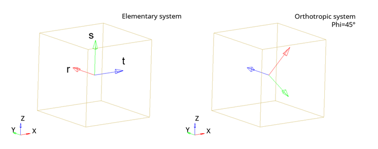
IP =3 The elementary direction s defines the third orthotropic direction. The first and second orthotropic directions are rotated by orthotropic angle in the plane (t,r). 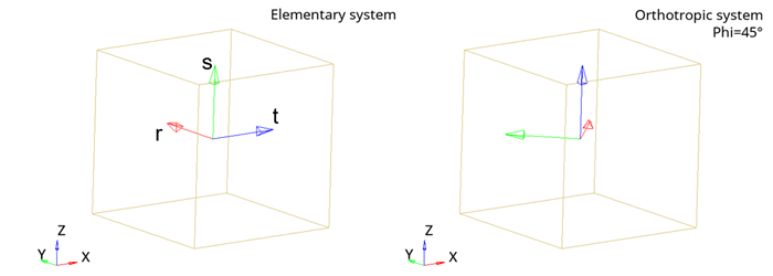
IP =11 The third orthotropic direction is normal to the plane (r,s). The first orthotropic direction is defined by vector V projected on plane (r,s).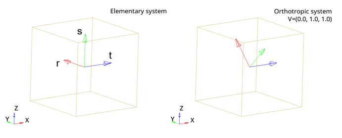
In case vector V can not be projected on the plane (r,s), default orientation is used.
IP =12 The third orthotropic direction is normal to the plane (s,t). The first orthotropic direction is defined by vector V projected on plane (s,t).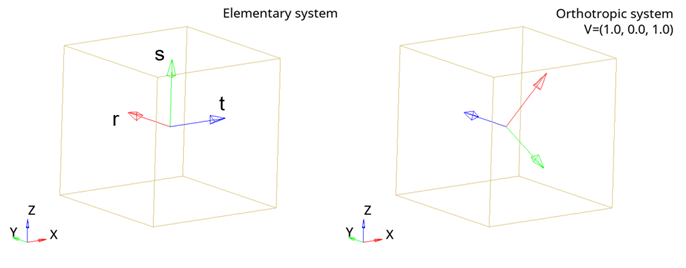
In case vector V can not be projected on the plane (s,t), default orientation is used.
IP =13 The third orthotropic direction is normal to the plane (t,r). The first orthotropic direction is defined by vector V projected on plane (t,r).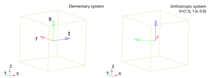
In case vector V can not be projected on the plane (t,r), default orientation is used.
IP =20 Orthotropic directions are from element connectivity (N1, N2, N4). 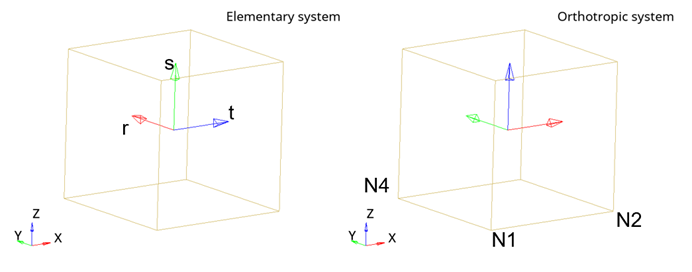
IP =21 First orthotropic direction is defined from point P and the center of the element. Second orthotropic direction is defined from global Z and the first orthotropic direction.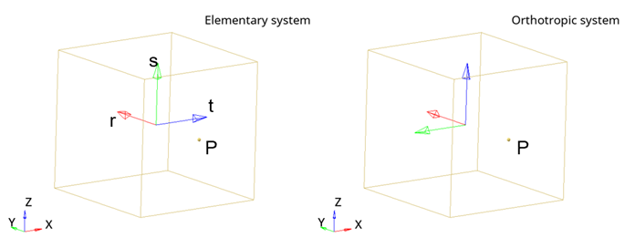
IP =23 Second orthotropic direction is defined from vector V. First orthotropic direction is defined from the second elementary direction and the second orthotropic direction.
First and second orthotropic directions are rotated by orthotropic angle .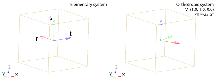
IP =24 Second orthotropic direction is defined from vector V. Third direction is defined by the projection of the center of the element onto the vector V, which passes through point P and the center of the element.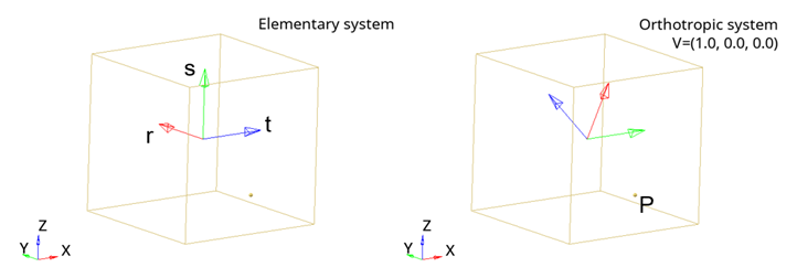
- For 2D solid elements
(/QUAD), there are two different ways to define
orthotropy direction:
- With Ip = 1, isoparametric system (r-s) and orthotropic angle are used. 10
- With Ip = 11, Reference vector is used: Global vector may be used to define the orthotropy direction. If this reference vector is orthogonal to plane, first axis of the plane (r-s) is taken as orthotropy direction.
Figure 5. 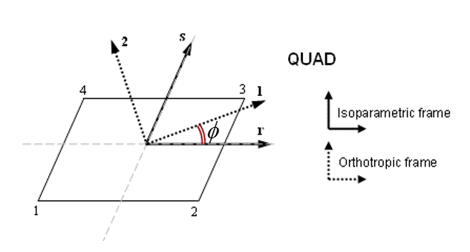
- Solid to SPH
properties (Sol2SPH)
- When using Sol2SPH, solid elements are converted to SPH particles when a solid is deleted due to contact, a material failure criteria or time step criteria.
- The number activated of SPH particles depends on parameter Ndir. The particles properties are computed using the sphpart_ID part number.
- Skew definition is not required in the SPH property as the skew definition and orientation is automatically transmitted from the solid to the particles. It is not advised to use the same SPH part ID for an isotropic and orthotropic Sol2SPH part.
The option Sol2SPH is only compatible with Isolid = 1, 2 or 24, Iframe = 1 or 2.
- The Isolid flag is not used with 4-node (/TETRA4) or 10-node (/TETRA10) tetrahedron elements.
- Quality criteria are
calculated as follows:
- Maximum Volume Ratio: If , then element is deleted;
- Maximum Volume Ratio: If , then element is deleted;
- Maximum Aspect Ratio: If
, then element is deleted with:
- Hexa: lmax calculated as max length of the 3 medians of the element
- Tetra: lmax calculated as the square root of the max area
- Solid: lmin calculated as lc
- Tshell: lmax calculated as max length of the 2 medians of the element
- Tshell: lmin calculated as the area of the middle surface divided by lmax
- Minimum Tetra Collapse: If , then element is deleted.
- The Icontrol flag is
issued to avoid negative volume for solid element with a total strain
formulation (Ismstr ≥ 10). This flag is recommended for soft material, compressible foam, rubber
materials. The following controls are activated with Icontrol=1 on the solid element:
- Add damping when there is high relative nodal velocity in the element.
- Add internal self-contact (node to solid segments)
- Set bigger hourglass stiffness (same as Isolid=5 formulation)
- Add deformation control for quadratic tetrahedron middle nodes (/TETRA10).