Power balance (Transient Magnetic application)
Introduction
In Transient Magnetic application, the resolution is carried out for each time step. The power balance is carried out for a time interval defined by the user.
Sub-systems definition: reminder
A system comprises one or more sub-systems as the one presented in the figure below.
![]()
Computation / results
For each of the sub-systems, as well as for the time interval defined by the user (Δt = t2 - t1), the following quantities are computed:
- the stored energies (instantaneous values, for t = t1 and for t = t2)
- the dissipated powers (mean values over the time interval Δt)
Stored energies
For the stored energies, a summary of the computed quantities is presented in the table below.
| Sub-system |
Stored energy (at a moment t) (in J) |
|
|---|---|---|
| Internal |
Magnetic energy stored in the computation domain: |
|
| Internal mechanical energy:
|
||
| Electrical |
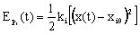
Energy stored in the coils:
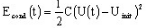
Energy stored in the capacitors:
|
|
| Mechanical |
External mechanical energy
|
|

Dissipated powers
For the dissipated powers, a summary of the calculated quantities is presented in the table below.
| Sub-system |
Losses (instantaneous values) (in W) |
Losses (mean values) (in W) |
|---|---|---|
| Internal |
Losses by Joule effect in solid conductors Losses by Joule effect in stranded conductors
|
|
|
Internal mechanical losses:
|
||
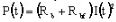
| Electrical | Losses by Joule effect (resistive
components):  |
|
| Mechanical |
External mechanical losses:
|