
Patch
Use the Patch tool to fill in a missing surface in the die.
-
On the Die Design ribbon, select the Defeature
tool.

-
Select the Patch tool.

The guide panel appears.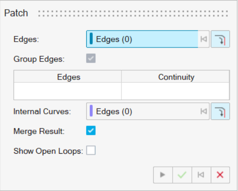
-
Next to Edges, the Select button is active. Select one
or more edges.
Note: To select all connected edges, turn on
 Select Connected Edges. When you select one edge, the
entire chain of edges is selected.
Select Connected Edges. When you select one edge, the
entire chain of edges is selected.To deselect, hold down Ctrl while clicking.
- To group the selected edges into a single edge set, turn on Group Edges. Turn off this option to define the continuity for each edge.
-
Define the Continuity for the Edge Sets:
- Position (G0): No constraints are set; the patch surface is connected to the surface edge, but not tangent to it.
- Tangent (G1): The patch surface is made tangent to the surface edge but does not follow the curvature of the adjacent surface. A box is displayed on the profile to indicate that a tangency constraint was applied.
- Curvature (G2): The patch surface is made tangent to the surface edge and follows the curvature of the adjacent surface. A circle is displayed on the profile to indicate that a curvature constraint was applied.
- Next to Internal Curves, the Select button is active. Select internal curves. To deselect, hold down Ctrl while clicking. To also select all the tangent edges when clicking an edge, turn on Tangent Propagation.
- To merge target and patch surfaces, turn on Merge Result. Turn off this option to make the patch a new part.
- To show all open loops, which could be patched, in the model, turn on Show Open Loops. Otherwise, turn off this option.
- Click Apply.
- Right-click and mouse through the check mark to exit, or double-right-click.