Create Hardpoints
Use the Hardpoints tool to define and manage non-design locations for topology optimization.
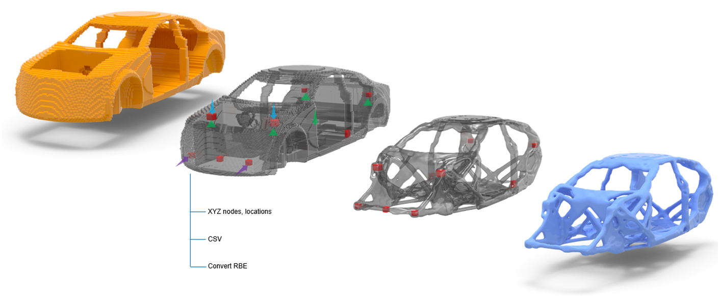
Once the hardpoint locations have been created, you can apply loads, boundary conditions, and the optimization problem definition. Once complete, topology optimization can be performed. It is recommended to have the loads, boundary conditions, and optimization problem definition in a separate include file for easy modular model setup.
-
From the Design Space ribbon, click the
Hardpoints tool.
Figure 2. 
- Select the design space.
-
Define hardpoints in one of the following ways.
Method Steps Manual Creation Define one or more locations using node selection or XYZ coordinates. - From the guide bar, select Nodes or Locations.
- Define one or more locations in the modeling window.
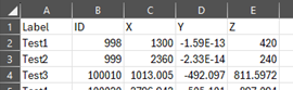
CSV Import Load hardpoint location data from a .csv file. - From the guide bar, click
Create from table.
The Hardpoints Manager dialog opens.
- Click
 and browse and
select a .csv file.
and browse and
select a .csv file.The contents of the .csv file is populated in the Hardpoints Manager dialog.
Tip: You can add and remove entries and save the .csv file for reuse. - Click Create Nodes
The locations are detected, the connector attachments are created, and the voxels in the design space are moved to a new non-design component.
Legacy Model Conversion Convert existing RBE elements into non-design hardpoints within an existing design space model. - From the guide bar, select Elements.
- Select existing RBE elements.
-
In the microdialog, select a shape.
Restriction: Shape selection is not available for RBE input.The capture options in the microdialog provide various settings to control dimensions and ensure accurate spatial capture.
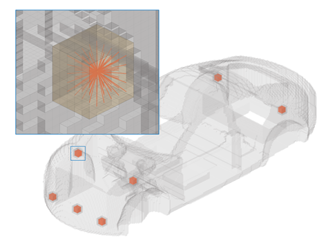
During the creation process, a connector attachment is established at the selected location, and an RBE is generated to link all voxels within the defined capture region.
Figure 4. 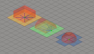
The voxels attached to the newly created RBE are organized into a new component. The new component does have an appropriate PSOLID property assigned, but, no DTPL assigned, hence non-design for topology optimization.
Figure 5. 
Connector attachments are created which preserves the record of the non-design setup parameters.
-
On the guide bar, complete one of the following:
- Click
 to apply and stay in the tool.
 - Click
 to apply and close the tool.
 - Click
 to exit the tool without applying.
- Click