
Outputs
Use the Outputs tool to configure a result output request for the solver. By default, Inspire automatically computes and stores standard simulation results. An output request is a user-defined instruction that directs the solver to compute and store additional, specific results. These results are typically used for plotting, reporting, or other post-processing activities.
Add an Output Request
To add an output, select the type of measurement—such as displacement, force, or a user-defined expression—then choose the entity or set of entities to measure.
-
On the Motion ribbon, under Profile, select Analyst.

-
Under Measure, select the Outputs tool.

Tip: To find and open a tool, press Ctrl+F. For more information, see Find and Search for Tools.The guide panel is displayed.Figure 2. 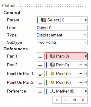
- Optional: To select a Parent system, click ....
- Optional: Edit the Label.
-
Select an output Type.
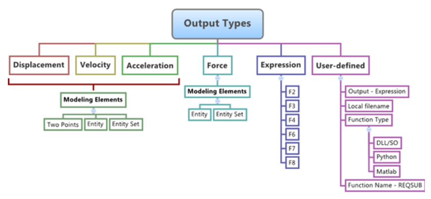
Table 1. Type Description Displacement Measures the absolute or relative position of bodies or markers. Velocity Measures the absolute or relative rate of change in the position of bodies or markers. Acceleration Measures the absolute or relative rate of change in the velocity of bodies or markers. Force Measures forces and torques acting on joint and force elements. Expression Provides measurements derived from user-defined expressions or functions that can incorporate system variables. User Defined Captures measurements computed through external user-defined subroutines. -
Select an output Subtype. The available options depends
on the output Type
Table 2. Subtype Description Two Points The output can be measured between two points that belong to two different bodies. Entity The output can be defined for an entity. The supported entities for this method of output are: body, joint, beam, bushing, field, force, spring damper, and contact. Entity Set The output can be defined for all entities of a certain type that are currently present in the model. The supported entities for this method of output are: body, joint, beam, bushing, field, force, spring damper, and contact. - Resolve the References collectors as per available choices. To edit the References, follow steps in the Edit an Output section.
-
Click Apply.
The entity appears in the Model Browser and its properties appear in the Property Editor.
- Right-click and mouse through the check mark to exit, or double-right-click.
Edit an Output
-
If the Outputs guide panel is not currently displayed,
select the desired output by double-clicking on the output entity in the
Model Browser.
The guide panel is automatically displayed.
- For Type, select the type of results that need to be extracted from the dropdown menu
-
Select a Subtype from the second drop-down menu.
There are three ways to define displacement/velocity/acceleration outputs between any two parts:
Option Description Two Points - Select Two Points from the Subtype drop-down menu.
- Resolve the Part 1 collector and pick the first part for the output request from the modeling windowor by using the Advanced selector....
- Similarly, resolve the Part 2 collector by selecting a part from the modeling window or by using the Advanced selector....
- Resolve the Point on Part 1 collector by clicking the point for the location on Part 1 in the modeling window or by using the Advanced selector....
- Resolve the Point on Part 2 collector by clicking the point for the location on Part 2 in the modeling window or by using the Advanced selector....
- Resolve the Reference collector by clicking on a marker in the modeling window or by using the Advanced selector ....
- Select I Marker,
J Marker, or
Both from the drop-down menu in the
Property Editor.
Selecting I Marker results in defining the output for Part 1 relative to Part 2 only. Selecting J Marker results in defining the output for Part 2 relative to Part 1 only. Selecting Both defines both of these outputs. Default is Both.
Note: The points and parts on which the output is requested cannot be pair entities.Entity - Select Entity from the Subtype drop-down menu.
- For Entity Type, select an option from
the drop-down menu.
- Body
- Joint
- Beam
- Bushing
- Field
- Force
- SpringDamper
- Resolve the entity collector (changes based on Entity Type selection) and pick the entity for the output request from the modeling window, or by using the Advanced selector....
- Resolve the Reference collector by clicking on a marker in the modeling window or by using the Advanced selector ....
- Optional: Select I Marker, J Marker, or Both from the drop-down menu in the Property Editor.
Entity Set - Select Entity Set from the Subtype drop-down menu.
- For Entity Set Type, select an option
from the drop-down menu.
- Bodies
- Joints
- Beams
- Bushings
- Fields
- Forces
- SpringDampers
- Resolve the Reference collector by clicking on a marker in the modeling window or by using the Advanced selector ....
There are two methods of defining force outputs:Option Description Entity - Select Entity from the Subtype drop-down menu.
- For Entity Type, select an option from
the drop-down menu.
- Body
- Joint
- Beam
- Bushing
- Field
- Force
- SpringDamper
- Contact
- Resolve the entity collector (changes based on Entity Type selection) and pick the entity for the output request from the modeling window, or by using the Advanced selector ....
- Resolve the Reference collector by clicking on a marker in the modeling window or by using the Advanced selector ....
- Optional: Select I
Marker, J Marker, or
Both from the drop-down menu in the
Property Editor.
Selecting I Marker results in defining the output for Part 1 relative to Part 2 only. Selecting J Marker results in defining the output for Part 2 relative to Part 1 only. Selecting Both defines both of these outputs. Default is Both.
Entity Set - Select Entity Set from the Subtype drop-down menu.
- For Entity Set Type, select an option
from the drop-down menu.
- Bodies
- Joints
- Beams
- Bushings
- Fields
- Forces
- SpringDampers
- Contacts
- Resolve the Reference collector by clicking on a marker in the modeling window or by using the Advanced selector ....
There are two methods of defining user-defined outputs:Option Description Expression - From the Type drop-down menu, select Expressions to create an expression based output request.
- Click inside any of the text boxes (F2, F3, F4, F6, F7, F8) and enter a solver expression that needs to be printed to the result files.
- Optional: Select the Define
custom names and units check box in the Property Editor in order to provide custom names
and units for the F2, F3… output channels.
- Additional columns (Cnames and Cunits) are available for entering the custom names and units.
- The custom names along with the units will appear as component names for the channels while plotting.
User-Defined - From the Type drop-down menu, select User Defined.
- Define the user subroutine in the Property Editor.
- Enter the user subroutine call expression with arguments in the User expr: text box.
- Select the Use local file and function name check box if the use of a local subroutine file is necessary.
- Select the subroutine file in the local system by clicking on the Local File: folder icon.
- From the Function Type drop-down menu, select the type of the subroutine file: DLL/SO, Python, MATLAB, or Compose.
- Enter the function name in the Function
Name: text box.
Inspire provides REQSUB as the default, which is the default function used by Inspire.
- Optional: Select the Define
custom names and units check box in the Property Editor in order to provide custom names
and units output channels returned by the subroutine.
- Additional tab Names/Units appears that contains Cnames and Cunits columns to enter the custom names and units.
- The custom names along with the units will appear as component names for the channels while plotting.