
Spring Dampers
Use the Springs tool to create and edit SpringDampers.
A SpringDamper can be a coil spring damper or a torsion spring damper.
- Coil Spring
- Generates a translational line of action force between two points on two bodies that is a function of the distance and the relative velocity between the two points.
- Torsion Spring
- Produces a moment between two bodies that is a function of the relative angular displacement and the relative angular velocity.
Add a Coil Spring Damper
- From the Model Browser, select the system to which the coil spring damper is to be added.
-
On the Motion ribbon, under Profile, select Analyst.

-
Under Forces, click the CoilSprings icon.

Tip: To find and open a tool, press Ctrl+F. For more information, see Find and Search for Tools.The guide panel is displayed.Figure 1. 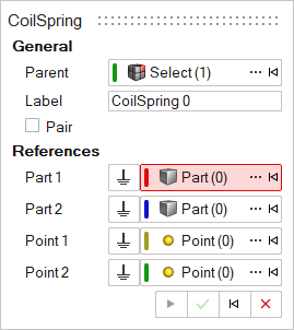
- Optional:
Select the Pair check box to create a pair entity.
A coil spring damper entity, like most of the entities that are created in Inspire, can be a single entity or a pair entity. Pair entities help to create models that are symmetric about the Z-X plane of the model. Their properties can also be symmetric about the Z-X plane (in other words, the Y property is mirrored). Asymmetry or symmetry of the coil spring damper can be decided or specified when editing the created coil spring damper.
-
Select the first part reference (Part 1).
- Select a part in the modeling window.
OR
- On the guide bar, click the Advanced
Selector
 and make your selection in the Model Tree.
Note: When defining a pair coil spring damper, use pair entities for Part 1, Part 2, and so on. - Select a part in the modeling window.
-
Select the second part reference (Part 2).
- Select a part in the modeling window.
OR
- On the guide bar, click the Advanced
Selector
and make your selection in the Model Tree.
- Select a part in the modeling window.
-
Select the first origin reference (Origin 1).
- Select an origin in the modeling window.
OR
- On the guide bar, click the Advanced
Selector
and make your selection in the Model Tree.
- Select an origin in the modeling window.
-
Select the second origin reference (Origin 2).
- Select an origin in the modeling window.
OR
- On the guide bar, click the Advanced
Selector
and make your selection in the Model Tree.
- Select an origin in the modeling window.
- Optional:
Click
 to reset the entity selections and select new
entities.
to reset the entity selections and select new
entities.
-
After the reference selections are made, create the coil spring damper using
one of the following methods:
- Click
 on the guide bar to
create and orient the entity.
on the guide bar to
create and orient the entity.OR
- Click the
 button that appears at the mouse
location in the modeling window.
button that appears at the mouse
location in the modeling window.OR
- Click
 to create the entity and exit the guide bar selections for this coil spring damper.
After the coil spring damper has been added to the model, the corresponding coil spring damper will automatically be displayed in the browser area.Note: By default, variables names of entities in Inspire follow a certain convention. For example, all coil spring damper entities have a variable name starting with “CoilSpring_”. This is the recommended convention to follow when building models in Inspire since it has many advantages in model editing and model manipulation. - Click
Add a Torsion Spring Damper
- From the Model Browser, select the system to which the torsion spring damper is to be added.
-
On the Motion ribbon, under Profile, select Analyst.
-
Under Forces, click the TorsionSprings icon. If
TorsionSprings is not visible, use the
 dropdown under the
CoilSprings tool.
dropdown under the
CoilSprings tool.
Tip: To find and open a tool, press Ctrl+F. For more information, see Find and Search for Tools.The guide panel is displayed.Figure 2. 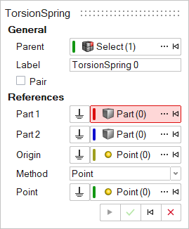
- Optional:
Select the Pair check box to create a pair entity.
A torsion spring damper entity, like most of the entities that are created in Inspire, can be a single entity or a pair entity. Pair entities help to create models that are symmetric about the Z-X plane of the model. Their properties can also be symmetric about the Z-X plane (in other words, the Y property is mirrored). Asymmetry or symmetry of the torsion spring damper can be decided or specified when editing the created torsion spring damper.
-
Select the first part reference (Part 1).
- Select a part in the modeling window.
OR
- On the guide bar, click the Advanced
Selector
and make your selection in the Model Tree.
Note: When defining a pair torsion spring damper, use pair entities for Part 1, Part 2, and so on. - Select a part in the modeling window.
-
Select the second part reference (Part 2).
- Select a part in the modeling window.
OR
- On the guide bar, click the Advanced
Selector
and make your selection in the Model Tree.
- Select a part in the modeling window.
-
Select a point origin reference (Origin).
- Select a point in the modeling window.
OR
- On the guide bar, click the Advanced
Selector
and make your selection in the Model Tree.
- Select a point in the modeling window.
- Optional:
Click to reset the entity selections and select new
entities.
-
Once the reference selections are made, create the torsion spring damper using
one of the following methods:
- Click on the guide bar to
create and orient the entity.
OR
- Click the button that appears at the mouse
location in the modeling window.
OR
- Click to create the entity and exit the guide bar selections for this torsion spring
damper.
Once the torsion spring damper has been added to the model, the corresponding torsion spring damper will automatically be displayed in the browser area.Note: By default, variables names of entities in Inspire follow a certain convention. For example, all torsion spring damper entities have a variable name starting with “TorsionSpring_”. This is the recommended convention to follow when building models in Inspire since it has many advantages in model editing and model manipulation. - Click
Edit a Spring Damper
- Select the spring damper.
-
Choose from the following methods:
Table 1. Edit methods To use this method Do this CoilSprings and TorsionSprings tools - On the Motion ribbon, under Profile, select
Analyst.
- Under Forces, click the
CoilSprings or
TorsionSprings icons.
- The CoilSprings or TorsionSprings guide panel appears.
- Activate the Part or Origin collectors that need editing.
- Pick a different part or origin either from the
modeling window or the
Advanced Selector
.
Property Editor - From the View menu, select Property Editor.
- On the Motion ribbon, under Profile, select
Analyst.
Spring Dampers Properties
Descriptions of spring dampers properties in the Property Editor.
The Property Editor displays the following properties that can be edited:
| Name | Description | ||
|---|---|---|---|
| General | |||
| Name | Descriptive name for the entity. | ||
| Variable Name | Variable name of the entity. | ||
| ID | Integer identifier. | ||
| Type | Type of spring – Coil or Torsion. Read only. | ||
| Body 1 | First body the spring is attached to. | ||
| Body 2 | Second body the spring is attached to. | ||
| Symmetry |
|
||
| For Coil Spring | |||
| Point 1 | Location at which the spring is attached to the first body. | ||
| Point 2 | Location at which the spring is attached to the second body. | ||
| For Torsion Spring | |||
| Origin | Torsion spring location. | ||
| Align Method | Method of aligning the torsion spring using either Point or Vector. | ||
| Point | If Align Method is Point, select the point as a direction along which the torsion spring is aligned. | ||
| Vector | If Align Method is Vector, select a vector as a direction along which the torsion spring is aligned. | ||
| Signal | |||
| User-defined | Activating the check box allows specifying the properties of the spring damper using user subroutines. | ||
| User expr | Expression defined with the USER solver function with parameters being passed to the user subroutine. | ||
| Use local file and function name | Activating the check box enables the definition of properties through a file. | ||
| Local file | Local file selection for the subroutine. | ||
| Function Type | Function type selection. | ||
| Function name | Function name definition. | ||
| Properties | |||
| Stiffness and Damping | |||
| Type | Select the type of force representation of stiffness. | ||
| Constant | Indicates a constant stiffness value for the spring. | ||
| Value | |||
| Spline | Indicates force due to stiffness is represented using a spline (Force/Torque v/s Deflection). | ||
| Spline | |||
| Interpolation | |||
| Independent variable | |||
| Spline3D | Indicates force due to stiffness is represented using a 3D spline (Force/Torque v/s displacement and another independent variable). | ||
| Spline3D (value) | |||
| Interpolation | |||
| Independent variable X | |||
| Independent variable Z | |||
| Expression | Indicates stiffness force input using a solver expression. | ||
| Expression | |||
| Preload | Initial force in the spring. Applicable only when Stiffness is of Type – Constant. See About Preloads below. | ||
| Off | |||
| Force/Torque | |||
| Length/Angle | |||
| Force and Length/Torque and Angle | |||
| Force (coil spring) | Value of force in model force units. Applicable only when the Preload Option is Force or Force and Length. | ||
| Length (coil spring) | Installed length of the coil spring in model length units. Default value is an expression measuring the distance between the two end points of the spring. Applicable only when the Preload Option is Length or Force and Length. | ||
| Force (torsion spring) | Value of torque in model force-length units. Applicable only when the Preload Option is Torque or Torque and Angle. | ||
| Angle (torsion spring) | Angular rotation in degrees installed as preload of the torsion spring. Applicable only when the Preload Option is Angle or Torque and Angle. | ||
| Appearance | |||
| For Coil Spring | |||
| Number of Coils | Number of coils in the spring graphic. | ||
| Radius | Radius of the spring graphic. | ||
| Show Spring Graphic | Check box to control visibility of coil spring graphic. | ||
| Show Damper Graphic | Check box to control visibility of damper graphic. | ||
| Color | Color of the spring damper graphic. | ||
| Distance between points | |||
| MAG | |||
About Preloads
- Preload is the initial force or torque in the spring in the modeled
position. The total preload can be specified by using either a Force/Torque
value, the Length/Angle value, or a combination of the two.
Figure 3. Fp = P + K *(Lo–l) where Fp is total preload K is the stiffness of the spring 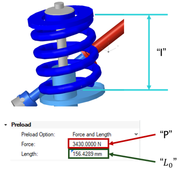
- The total preload Fp is
applied as the summation of Force P and the force due to
change in length K *(Lo
–l); where K is the stiffness,
Lo is the free length,
and l is the modeled length of the spring (refer to the
figure above).
- For example, if the two end points of the defined spring (modeled length of spring) is 100 mm and the free-length is specified as 110, that represents the spring in a pre-deflected state by 10mm and the effective preload is 10 * K; where K is the stiffness of the spring.
- If the Preload value is specified in addition, this force is also added to the total preload.
- In another example, if the two end points of the defined spring (modeled length of spring) is 100 mm and the free-length is 0.0, that means in the current state the spring is in an extended state by 100mm and the preload to that effect (-100 * K) is applied.
- Inspire creates a coil spring damper with a default value free-length as the distance between two end points.
- For a torsion spring the total preload torque is applied as the summation of Torque P and the torque due to initial angle; K * (a) where K is the stiffness and a is the initial angle.
Note: If the selected spring damper is a pair entity, first
distinguish between the Left and Right
side in the property editor, and then edit the properties. When defining a pair
spring damper, use pair entities for Bodies and Points.
Tip: Use the Symmetry option to
adjust the symmetry of spring dampers’ properties. Specifically, this option will
determine if the pair entity is symmetric. If yes, then it is also responsible for
specifying which side of the values of the pair entity (left or right) is to be
used, by selecting Left or Right. Selecting
any one side will make values of that side as “leader” and the values of the other
side ("follower") will gray out and follow the values on the leader side.
SpringDamper is a force element that applies Line of action forces on two bodies based on stiffness and damping.
Constant SpringDampers are written to Inspire as Force Bushing (XML) or Bushing (msolve). When any stiffness or damping is not constant, bushing is written as a Force Vector TwoBody (XML) or GForce (msolve).