Tutorial Level: Beginner Learn how to create connections, add a motion and spring damper force, create a flexible
body and run a motion analysis.
In this lesson you will learn how to:
Ground a part
Create a rigid group
Connect parts with joints
Determine the direction of gravity
Add a motion to the model
Apply a spring-damper force
Add a flexible body
Review flexible body stress
Run a motion analysis
Open the CAD model
Press F7 to open the Demo Browser.
Double-click the M01_FourBar.x_t file in the Motion folder
to load it in the modeling window.
If not already visible, press F2 to open the Model
Browser.
Check that the display units are set to MKS.
Under File > Preferences > Inspire Motion > Run Options
change the solver units to MKS.
To switch to the Motion Analyst ribbon, click the dropdown under Profile and
select Analyst.
Ground a Part
On the Motion ribbon, select the
Ground tool from the Connections category.
Select the Base part to ground it.
The part turns red, and the part icon in the Model Browser changes to indicate that it is a ground part.
Right-click and mouse through the check mark to exit, or double-right-click.
Create a Rigid Group
Select the Rigid Groups tool.
Select the Base, Mount Crank, and
Mount Clevis parts in the bottom half of the
mechanism.
The parts turn red as you select them.
Click the floating Create New Group icon to place the
parts you selected into a new rigid group.
Right-click and mouse through the check mark to exit, or double-right-click.
Run a Simple Motion Analysis
Click the Quick Run button on the Analyze Motion tool to
see the model in motion.
Notice that the ground parts remain stationary and some of the unconnected
parts fall due to gravity.
Note: The Quick Run is a toggle button, so you can also use it to stop an
analysis that is still running.
After the analysis has stopped running, the icon appears and you are automatically placed into
review mode. Click the Review Motion Results icon or
double-right-click to exit review mode.
Connect Parts with Joints
Select the Joints tool on the Motion Analyst
ribbon.
The joints dialog appears with Revolute as the
default joint Type and Part 1 collector preselected.
In the modeling window, click on the Link
Crank part.
Click on the Mount Crank part.
Click the snap point at the center of the Mount Crank
hole.
Figure 1.
To define the orientation, select the dropdown next to Method and select
Vector.
Click the Advanced Selector ... in the
Vector collector.
In the Advanced Selector window, select Global Y and
click OK.
Click Accept to create
the joint.
Right-click and mouse through the check mark to exit, or double-right-click.
Note:
After clicking Accept, the context remains in
edit mode where you are free to make changes to the joint definition
by first clicking on the appropriate collector in the dialog and
then selecting the entity from the modeling window.
Using geometry snap points to define entities such as Origin, Point
or Vector results in the creation of a new entity in the model.
These new entities can be re-used as references for defining other
joints, forces, motions, etc.
If a collector is already populated with an entity, clicking on it
will highlight the entity (part, point or vector) in the modeling window for visual clarification.
Left-click in the modeling window to reset all
collectors and begin creating a new joint.
Notice the Label auto-indexes by 1 to now read Joint
1.
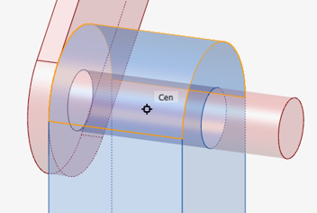
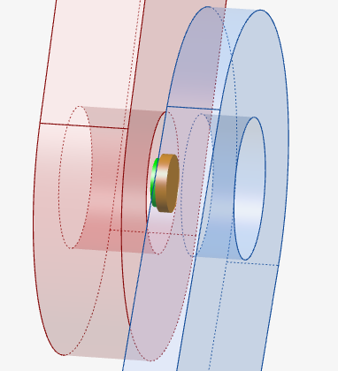
Repeat the steps 3 through 8 and add a Revolute joint between the
Link Crank and Link Single
Slot parts. Use the hole center snap point, as shown, when
defining the origin.
Figure 2.
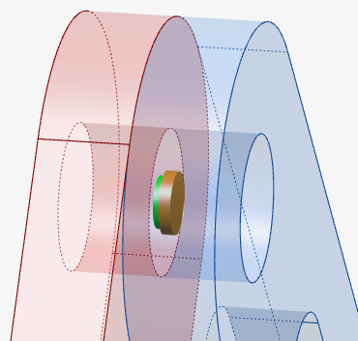
Repeat steps 3 through 8 and add a Revolute joint between the Link
Single Slot and Link Dual Slot.
Figure 3.
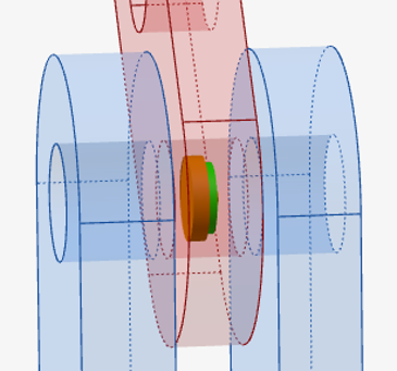
Repeat steps 3 through 8 and add a Revolute joint between the Link
Dual Slot and Mount Clevis parts.
Figure 4.
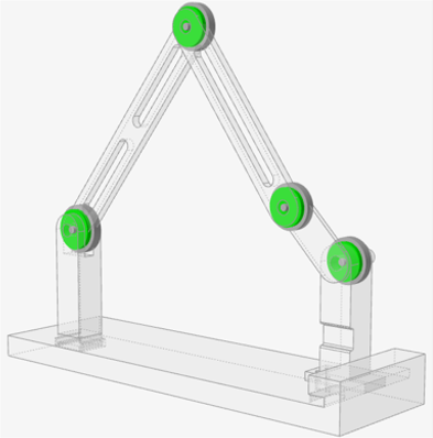
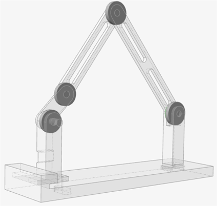
When finished, the
model should appear as follows:Figure 5.
Note: The scaling factor for joint graphics can be changed in
Preferences > Inspire Motion > Visualization > Scaling
factor for Analyst joints. In the image, the joints were scaled to
65.
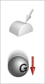
Inspect the Gravity Direction
Open the Gravity tool:
On the Motion ribbon, under Forces, select the
Gravity tool.
If
Gravity is not visible, use the dropdown under the
Forces tool).
By default, the gravitational acceleration (G) is set to 9.80665
m/s2 in the -z
direction.
Notice that a vector is displayed which indicates the direction of
gravity.
Figure 6.
Right-click and mouse through the check mark to exit, or double-right-click.
Change the Run Settings and Rerun the Analysis
Hover over the Analyze Motion tool, then click the
Run Settings icon to open the Run Motion Analysis
window.
Change the Output Rate to 100 by
entering the value in the field or clicking the 100
button.
Figure 7.
Expand the Gravity section and verify that the
Yes radio button is selected.
This is the default setting for a motion analysis.
Close the Run Motion Analysis window.
Click the Quick Run button on the Analyze Motion tool to
see movement of the model with the joint connections in place.
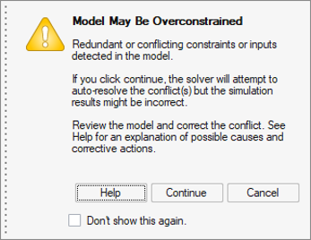
A message will appear warning of redundant constraints. This is because we
have all rigid bodies in the model and the combination of four revolute with
three rigid bodies is over-constraining the model. There are different ways to
resolve redundant constraints, but shortly we will address it by replacing a
rigid part with a flexible body.Figure 8.
Click Continue.
Click the Quick Run button again to stop the
analysis.
Double-right-click to exit review mode.
Add a Motion to Drive the Mechanism
Select the Motions tool.
In the dialog, set Define Motion to On Joint.
Set the Type to Velocity.
Click on the joint connecting the Mount Crank and
Link Crank.
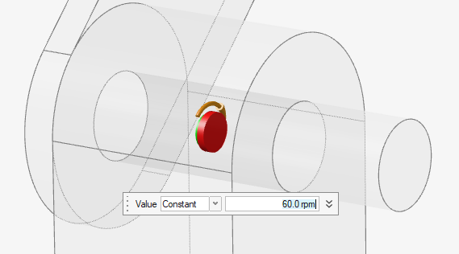
Click Accept to create the motion.
A microdialog will appear as well as a rotational arrow graphic on the
joint.Figure 9.
In the microdialog that appears, enter 60 rpm.
Add a Spring-Damper Force
Select the Coil Spring tool.
Select the Link Dual Slot part.
Select the Base part.
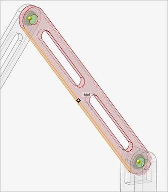
Click the Mid (middle) edge snap point of the
Link Dual Slot part.
The selected feature turns red.Figure 10.
Click the Mid (middle) edge snap point of the
Base part.
Figure 11.
Click Accept to create
the spring.
A coil spring appears and the microdialog shows the default
settings.
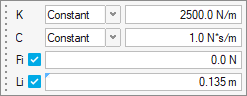
In the microdialog that appears, change the K stiffness
value to 2500 N/m and C Damping to
1 N*s/m. Leave the Force and
Length options as the defaults.
Figure 12.
Click and drag the white arrow manipulator to reduce the spring diameter to
.01 m.
Right-click and mouse through the check mark to exit, or double-right-click.
Change the Run Settings and Rerun the Analysis
Click the Run Settings icon.
Change the End Time to 2 s by entering the value in the
field or clicking the 2 button.
Close the window.
Click the Quick Run button, then click
Continue on the Redundant Constraint message dialog,
to see movement of the model.
After two seconds, the run will complete and you will automatically be placed
into the Review Motion Results tool.
Optional: Click the Play button on the animation toolbar
to review the results.
Left-click and swipe to exit the animation context.
Create a Flexible Body
One preferred way to remove redundant constraints from the model is to use flexible
bodies in place of rigid bodies. In this four bar example, we only need to replace
one of the links to break the redundancies in the system.
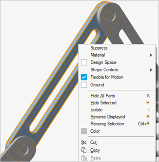
Right-click on the Link single slot.
Select Flexible for Motion from the panel.
The part will turn light blue.Figure 13.
Rerun the Motion Analysis
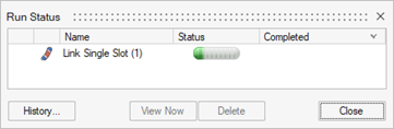
Click the Quick Run button.
Prior to running the motion analysis, the flex body will be created, as
shown by the Run Status window.Figure 14. Notice the Redundant Constraints warning message did not appear.
2. When the simulation is complete, click Close in the
Run Status window.
Under the Review tools in the Motion Analyst ribbon, click the dropdown menu.
Select the Review Flexible Body Results tool.
Figure 15.
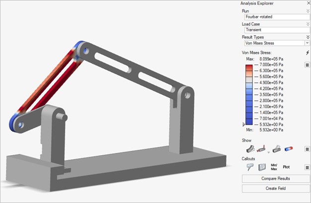
The Analysis Explorer will display.
In the Analysis Explorer, change Result Types to VonMises
Stress.
In the color legend, click on the maximum value in the legend (8e5 Pa) and
enter 7e5 (to better see stress contours).
Drag the animation slider to replay the animation and see stress change during
the mechanism movement.
Figure 16.
Left-click and swipe to exit the Analysis Explorer.
Plot the Motion Results
Click on the blue check mark (Review Motion Results)
next to the Analyze Motion icon.
Change the Time on the animation toolbar to
0.73 s by dragging the slider bar.
Figure 17.
Select Coil Spring 0 in the modeling window to see a
plot of the spring forces.
Figure 18.
Select Motion 0 from the Model Browser to see a plot of
the motion's output.
Figure 19.
In the motion's plot, click the TX, TZ and TM to hide them and only show
TY.
In the Model Browser, select the pin connecting the Link Single
Slot to the Link Dual Slot to view a
force plot for the pin.
Figure 20.
Note: Right-click on the plot to view other components that can be
plotted.
Right-click and mouse through the check mark to exit, or double-right-click.


 changes to indicate that it is a ground part.


 icon appears and you are automatically placed into
review mode. Click the Review Motion Results icon or
double-right-click to exit review mode.
icon appears and you are automatically placed into
review mode. Click the Review Motion Results icon or
double-right-click to exit review mode.


 to create
the joint.
to create
the joint.
 dropdown under the
Forces tool).By default, the gravitational acceleration (G) is set to 9.80665 m/s2 in the -z direction.
dropdown under the
Forces tool).By default, the gravitational acceleration (G) is set to 9.80665 m/s2 in the -z direction.