Tutorial: Gravity Casting
Tutorial Level: Beginner Run a simulation of a gravity casting adjusting different components to see the effects on the results.
In this exercise, you will learn about the process of gravity casting and the effect different components have on the finished part.
Model file is available in the tutorial_models folder in the installation directory in Program Files\Altair\2025\InspireCast2025\tutorial_models\gravity.x_b.
Import Geometry
- Launch Inspire Cast.
-
Click Open Model on the Files icon and browse to the
tutorial model file in the installation directory, or drag-and-drop the file
into the modeling window.

Designate a Casting Part
-
On the Cast Part icon, click Designate
Casting Part.

-
Left-click to select which candidate is a cast part.
Parts are automatically detected and highlighted based on your cursor position.The selected part is highlighted red.
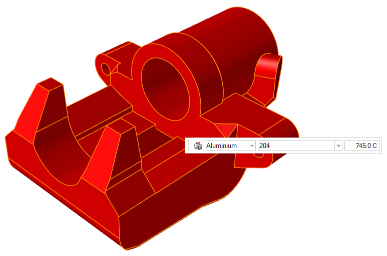
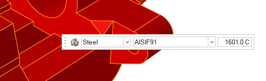
-
In the microdialog, select Steel
as the material and select AISIF91 as the alloy for the
part.
- Right-click and mouse through the check mark to exit, or double-right-click.
Set Gravity Direction
-
On the Cast Part tool, click Set Gravity
Direction.

-
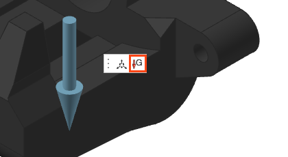
Click the Gravity icon in the microdialog to align gravity to the normal of a selected
surface.
-
Click on one of the bottom surfaces of the part.
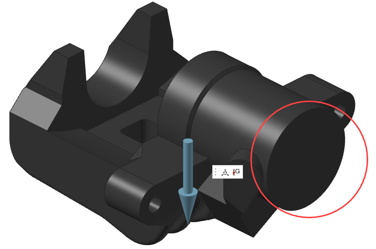 Gravity will automatically be realigned perpendicular to the selected surface.
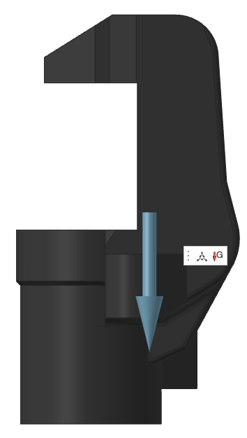
- Right-click and mouse through the check mark to exit, or double-right-click.
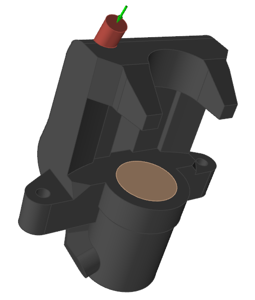
Add a Gate
- Click the Casting tab.
-
On the Gate icon, click Add/Edit
Gate.

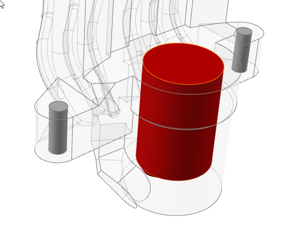
-
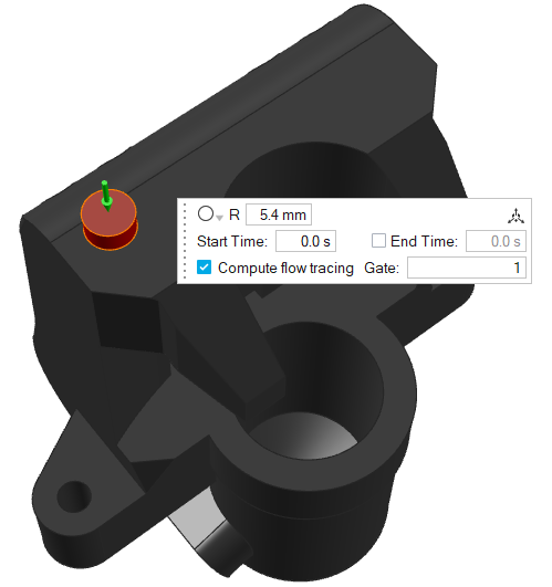
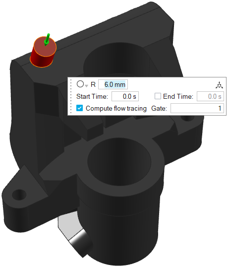
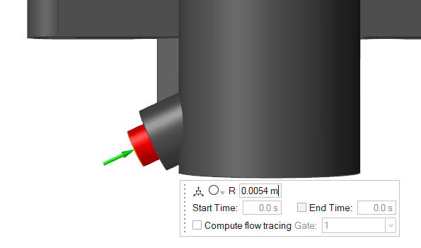
Select the top surface of the model to place a gate there.
-
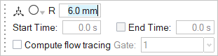
Change the radius of the inlet area to 6mm.
-
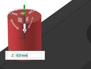
Click the Move
 icon.
icon.
-
Select the Z arrow and drag the inlet height to -8mm .
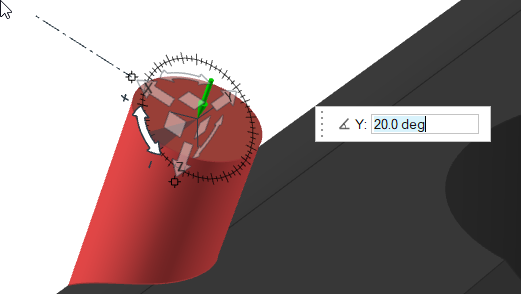
-
Select and drag the Y rotation arrow to tilt the inlet to
20º.
-
Right-click and mouse through the check mark to exit, or double-right-click.
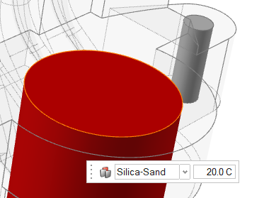
Add a Core
-
Click the Components tool.

Click the Core tool in the secondary tool group.
-
Cavities that can become cores are shown in gray. Click to select which
candidate is a core and automatically create the core volume.
The selected part is highlighted red.
-
In the microdialog, select
Silica-Sand as the material.
- Right-click and mouse through the check mark to exit, or double-right-click.
Add a Mold
-
Click the Components tool.
Click the Mold tool in the secondary tool group.
A mold is generated creating a bounding box of the components already edited.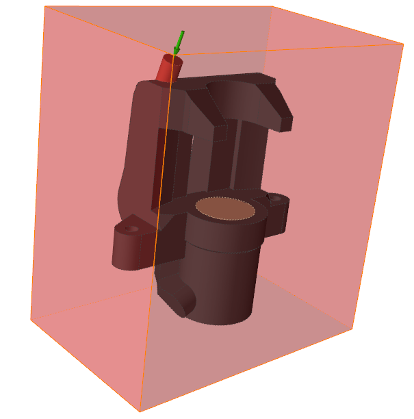
- In the microdialog, select Green-Sand as the material and 20° C for the temperature of the new mold.
- Right-click and mouse through the check mark to exit, or double-right-click.
Define Process Parameters
-
Click Basic Setup to enter the simulation
parameters.

-
Enter 1000 mm/s for Initial
Velocity.
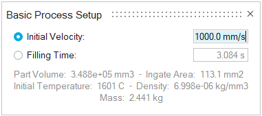
Note: This will be the velocity at the inlet for the duration of the filling of the mold cavity.
Run Analysis
-
On the Analysis icon, click Run
Analysis.

-
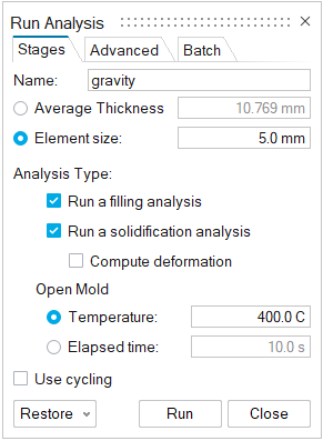
In the Run Analysis dialog, select the
Stages tab and enter the Element
size manually or define the Average
Thickness. You can also select number of cycles in the process
by selecting Use cycling.
-
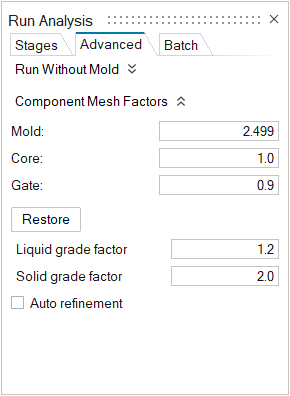
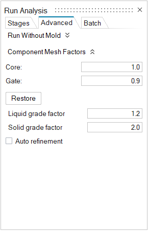
Select the Advanced tab to manually select mesh factors
for components like gate, mold, runner, riser, etc.
-
Select the Stages tab and click
Run.
Note: Once the simulation calculation is finished, a green flag will appear on the analyze icon.

Analyze Results
- Click the green flag to open the Analysis Explorer.
-
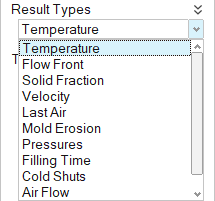
In the Analysis Explorer, click Temperature under
Result Types.
-
Click Play
to start the animation.

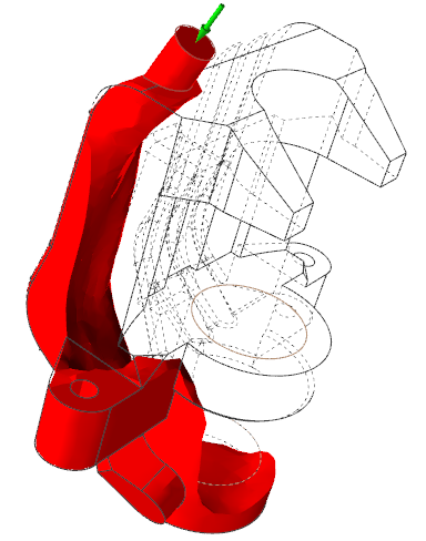
Temperature results show temperature evolution during filling, but they are also very useful to analyze the behavior of the fluid entering into the mold.
Here we can observe how the liquid is falling from the top to the bottom which can result in turbulence.
-
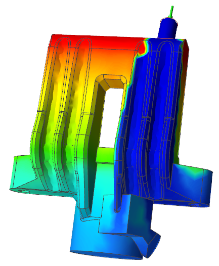
Click Filling time under Result
Types.
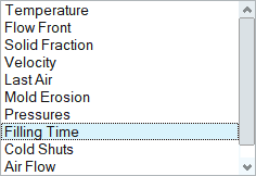
Filling time shows the time it takes the material to reach different areas within the part and is also useful to analyze the behavior of the liquid entering the mold.
Here we can see the differences in time to fill the right and left regions, so we will change the inlet position to avoid this issue.
- Right-click and mouse through the check mark to exit, or double-right-click.
Edit the Gate
-
Select the ingate and press Delete.
-
On the Gate icon, click Add/Edit
Gate.
-
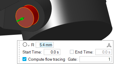
Select the center of this surface to create an inlet at the bottom of the geometry.
-
Right-click and mouse through the check mark to exit, or double-right-click.
Run Analysis
-
On the Analysis icon, click Run
Analysis.
-
In the Run Analysis dialog, select the
Stages tab and enter the Element
size manually or define the Average
Thickness. You can also select number of cycles in the process
by selecting Use cycling.
-
Select the Advanced tab to manually select mesh factors
for components like gate, mold, runner, riser, etc.
-
Select the Stages tab and click
Run.
Note: Once the simulation calculation is finished, a green flag will appear on the analyze icon.
Analyze Results
- Click the green flag to open the Analysis Explorer.
-
In the Analysis Explorer, click Temperature under
Result Types.
-
Click Play
to start the animation.
We can observe that the liquid is more stable entering the mold. The fluid rises homogeneously and without turbulence.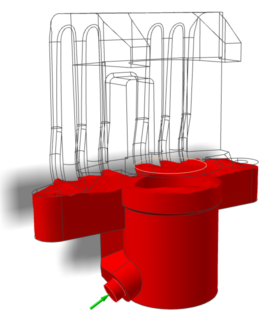
-
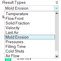
Click Mold Erosion under Result
Types.
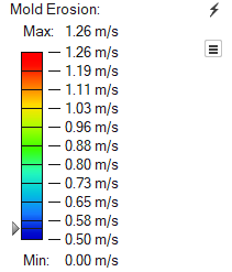
-
Set the minimum value to 0.50 m/s and slide the arrow up
to 0.54 m/s.
Mold erosion results allow you to predict which areas will exhibit excessive mold degradation due to high velocities.Here we see that the liquid is directly colliding with the sand core because of the inlet design.
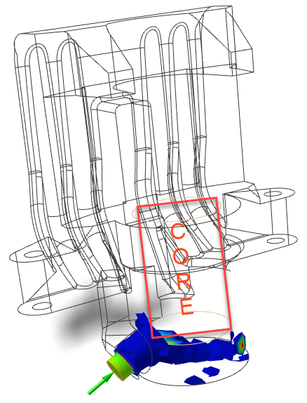
To avoid this problem, we will change the inlet angle.
-
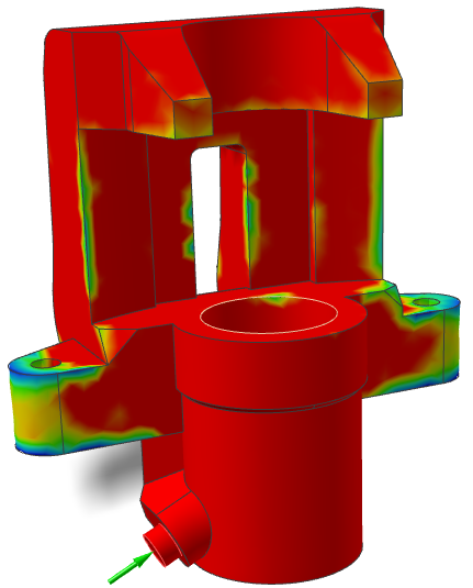
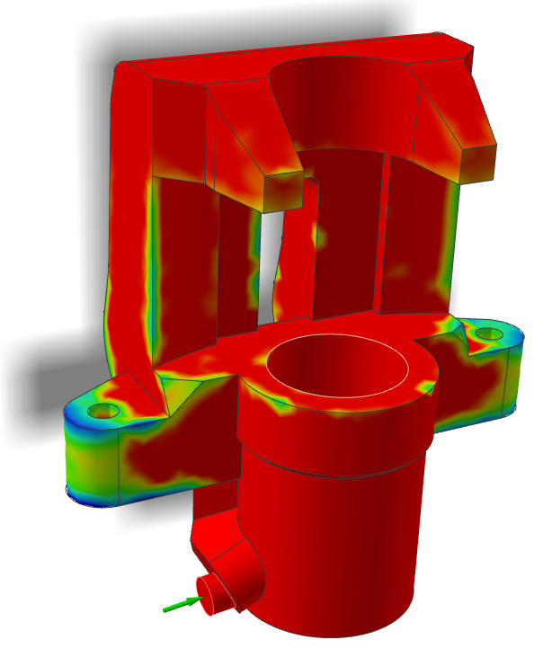
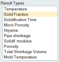
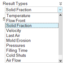
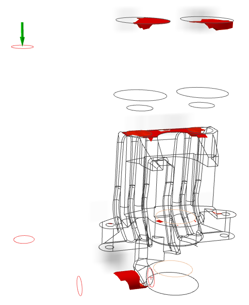
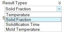
Click Solid Fraction under Result
Types.
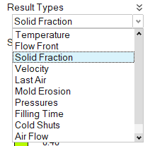
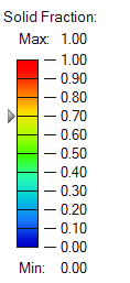
Solid Fraction results allow you to determine if there will be any solid areas during filling. A value of 0 corresponds to a completely liquid material, while a value of 1 corresponds to a completely solid material.
Here, there are no solidified areas during filling, so we can decrease the inlet velocity to avoid the direct collision with the sand core.
- Right-click and mouse through the check mark to exit, or double-right-click.
Edit the Gate
-
In the modeling window, double-click the ingate. Then, in the microdialog,
click Move
.
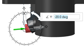
-
Select and drag the X rotation arrow to tilt the inlet to
-20º.
-
Right-click and mouse through the check mark to exit, or double-right-click.
Run Analysis
-
On the Analysis icon, click Run
Analysis.
-
In the Run Analysis dialog, select the
Advanced tab to manually select mesh factors for
components like gate, mold, runner, riser, etc.
-
In the Stages tab, click
Run.
Note: Once the simulation calculation is finished, the green flag will appear on the analyze icon.
Note: The user can also select the results by clicking View Now under Run History.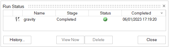
Analyze Results
-
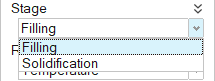
Click Filling under Stage.
-
Click Temperature under Result
Types.
-
Click Play
to start the animation.
Thanks to the change in the angle of attack of the inlet and to the velocity reduction, the liquid is not directly colliding against the sand core.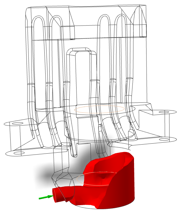
-
Click Solid Fraction under Result
Types.
Solid Fraction results allow you to determine if there will be any solid areas during filling. A value of 0 corresponds to a completely liquid material, while a value of 1 corresponds to a completely solid material.
Even though we reduced the velocity at the inlet and the filling time increased, there is no increase in solidification during filling.
-
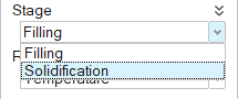
Click Solidification under
Stage.
-
Click Solid Fraction under Result
Types.
-
Click Play to start the animation.
Solid Fraction results allow you to understand that solidification behavior within the part. The default value of 0.7 corresponds to the value at which liquid stops flowing in most cases.Solidified material (above 0.7) is transparent, while liquid material (below 0.7) is shown in color. Shrinkage porosity is more likely to occur in isolated liquid regions.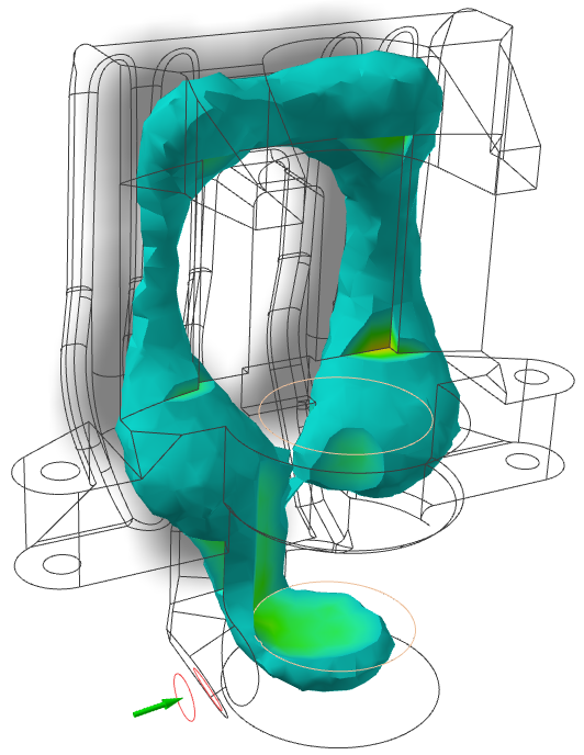
- Right-click and mouse through the check mark to exit, or double-right-click.
Design the Filling System
- Select the gate and press Delete.
- Click the Sketch tab.
-
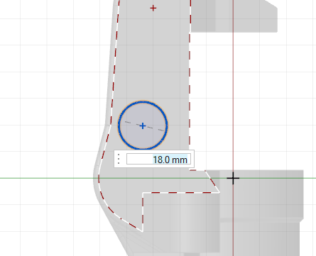
On the Circles icon, click Circle by Center
and Point.

- Click the surface to create the sketch plane.
-
Click on the surface shown and drag to create a circle with a diameter of 18 mm.
- Click the Geometry tab.
-
Select the Push/Pull Faces tool.

-
Select the circle we just created and pull it to a length of 70
mm.
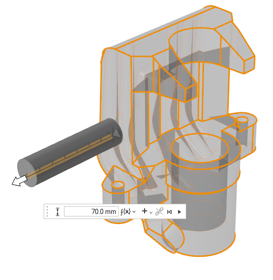
-
In the microdialog, ensure that Create New Part is
selected.
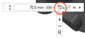
- Click Apply.
Reposition the Cylinder
-
In the Home ribbon, Click the Move icon.

-
Select the cylinder.
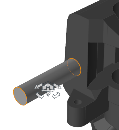
-
Click on the center of the end of the cylinder and drag the cylinder to the
center of the surface where we had previously created the ingate.
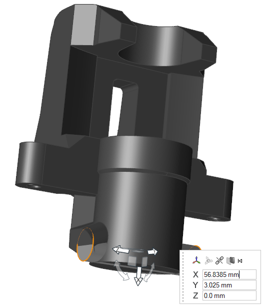
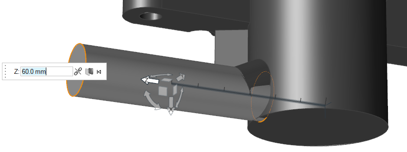
-
Select the Z arrow and move the cylinder along the Z axis
60mm.
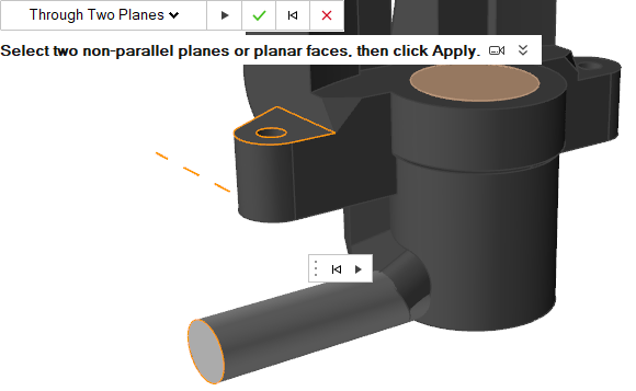
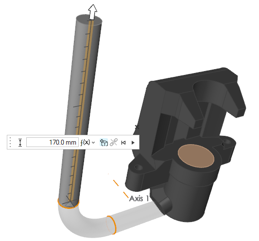
Rotate the Axis
-
Create a reference axis.
-
Click Reference Axes.

-
Select the end of the cylinder and the top surface of the flange, as
shown in the image below.
-
Click Apply
 .
.
-
Click Reference Axes.
-
Under the Extrude icon, click Revolve
Face.

- Select the end surface of the cylinder to revolve.
- Select the reference axis as the rotation axis.
-
Rotate the surface 90°.
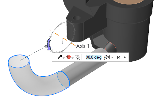
-
Ensure that Combine is selected.

- Click Apply.
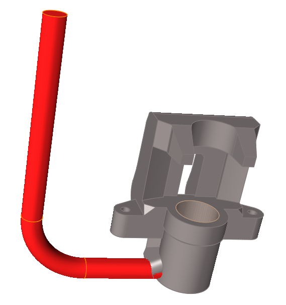
Pull the Surface
-
Click the Push/Pull icon.
-
Select the cylinder's surface. In the microdialog, click Create New
Part.
-
Pull the surface until the new cylinder reaches 170mm
long.
- Click Apply.
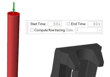
Create an Inlet
- Click the Casting tab.
-
On the Cast Part icon, click Designate
Filling System.

-
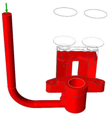
Select the geometry we just designed.
-
On the the Gate icon, click Designate
Surfaces as Gates.

-
Select the top surface of the filling system to create the inlet.
Create a Riser
-
Click the Components icon.
-
On the Riser icon, click Add/Edit
Riser.

-
Click on the region where there were issues with porosity.
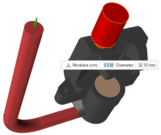
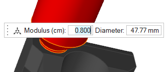
-
Change the Modulus to 0.8
cm.
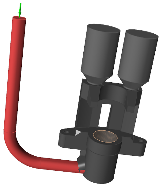
-
Repeat these steps to create a second riser.
Re-create the Mold
- In the modeling window, select the mold component.
- On your keyboard, press the Delete key.
-
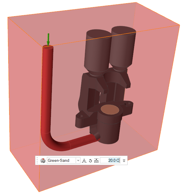
In the Components subribbon, click the Mold tool.

-
In the microdialog, select Green-Sand as the mold's material and set its
initial temperature to 20 degrees C.
- Right-click and mouse through the check mark to exit, or double-right-click.
Run Analysis
-
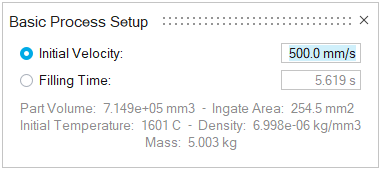
Click the Basic Setup icon.

-
Change the initial velocity to 500 mm/s.
-
On the Analysis icon, click Run
Analysis.
-
In the Run Analysis dialog, select the
Advanced tab to manually select mesh factors for
components like gate, mold, runner, riser, etc.
-
Click Run.
Note: Once the simulation calculation is finished, the green flag will appear on the analyze icon.
Note: The user can also select the results by clicking View Now under Run History.
Run the Temperature Animation
-
Click Filling under Stage.
-
Click Temperature under Result
Types.
-
Click Play to start the animation.
Note: We can see that the liquid is entering the mold smoothly and homogeneously avoiding turbulence and direct collision with the sand core thanks to the new inlet position and the newly designed filling system.
Run Solid Fraction Animation
-
Click Solid Fraction under Result
Types.
-
Click Play to start the animation.
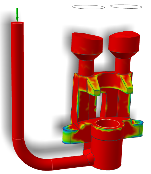
Note: It is important to not have early solidification during filling to avoid casting defects like misruns. In our case, it looks like it is filling in less than 6 seconds and not giving us this problem as there are no solidified areas during filling.
View Last Air Result
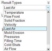
Run Solid Fraction Animation
-
Click Solidification under
Stage.
-
Click Solid Fraction under Result
Types.
-
Set the percentage to 0.7%.
-
Click Play to start the animation.
Note: We can see how the risers are feeding material to the top region during solidification.
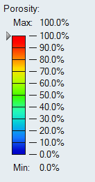
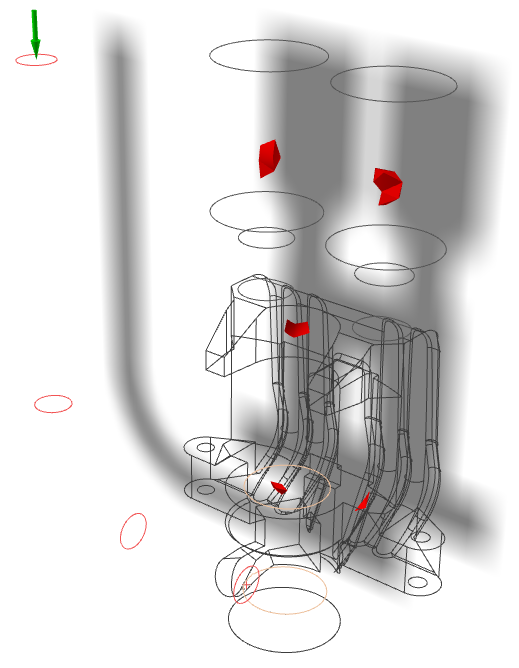
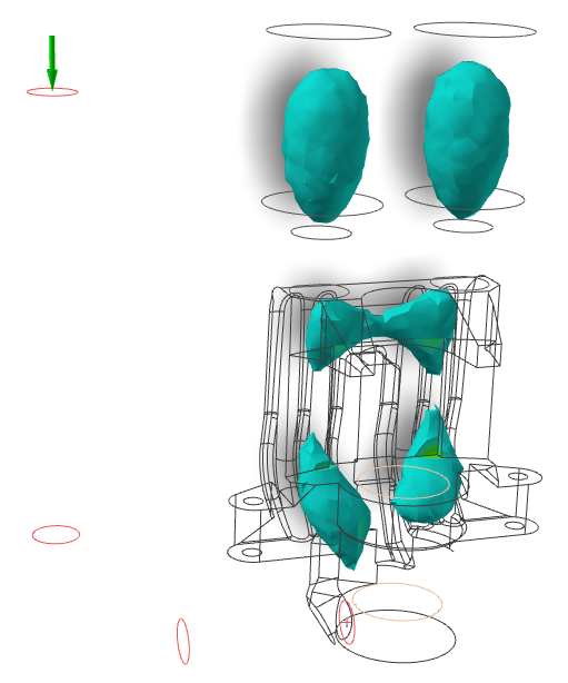
View Porosity Result
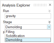
-
Click Demolding under
Stages.
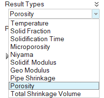
-
Click Porosity under Result
Types.
-
Set the percentage to 100%.