Reference entities: point, line, plane
Introduction
A reference entity provides some support to the construction of the geometry without being taken into consideration during the mesh and solving operations. These entities are of « NO_EXIST » type.
It exists several “Reference” entities:
- Reference point
- Reference line defined between two points
- Reference plane
When use it?
The table below presents when reference entities can be used.
| Reference Entities | When to use it ? |
|---|---|
| Reference point |
|
| Reference line |
|
| Reference plane |
|
How to create it?
The table below presents how the reference entities can be created.
| Reference Entities | How to create it? |
|---|---|
| Reference point |
The creation of a reference point is identical to the creation of a standard point of Flux. It is necessary to define the coordinate system of creation and coordinates of the point ((X Y Z). To create a reference point:
|
| Reference line |
The creation of a reference line is identical to the creation of a standard line of Flux of segment type. It is necessary to define two points of the segment. These points can be standard points of objects or reference points previously created.
|
| Reference plane |
The creation of a reference plane contains several type of definition (see below)
|
Type of reference plane
The table below shows different types of creation of a reference plane
| Type | Description | Illustration |
|---|---|---|
| Defined by a face (flat) | The reference plane is positioned on the plane of the face which must be flat |
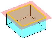
|
| Defined by a point and a line | The reference plane is positioned on the plane describe by the selected point and both points of the selected line (the line must be a segment type) |
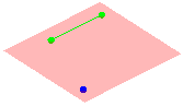
|
| Defined by 3 points | The reference plane is positioned on the plane describe by 3 selected points |
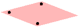
|
| Defined by a point and a line perpendicular | The reference plane is positioned on the plane describe by the orthogonal projection on the trajectory of the selected line |
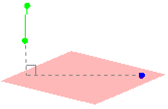
|
| XY plane with offset | The reference plane is positioned parallel to the XY plane with an offset |
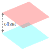
|
| XZ plane with offset | The reference plane is positioned parallel to the XZ plane with an offset | |
| YZ plane with offset | The reference plane is positioned parallel to the YZ plane with an offset | |
| Plane parallel to a plane | The reference plane is positioned parallel to the selected reference plane with an offset | |
| Defined by equation | The reference plane is positioned on the plane describe by the equation Ax + Bx + Cx = D. The user must choose coefficients A, B, C and D | |
| Defined by angle between two planes | The reference plane is positioned with an angle in relation to the selected reference plane around an axis (the selected line) |
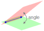
|
Predefined reference planes
Here is the list of predefined reference plane available at the opening of the modeler:
- XY plane
- XZ plane
- YZ plane
Corresponding coordinate system
For each creation of reference plane (REFERENCEPLANE_1) a corresponding coordinate system (COORDSYS_REFERENCEPLANE_1) is created.