Tutorial Level: Advanced DriveAer
model morphing with HyperMesh CFD.
In this tutorial, you are going to create a series of morph shapes for a vehicle
model in HyperMesh CFD Design Exploration environment. Any pre-processing procedures
required for the model have already been completed in the Geometry Repair
environment.
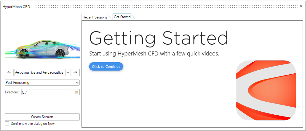
Solution and Environment Selection
When opening HMCFD, the Create Session dialog will appear. Select the
Design Exploration environment.
Figure 1.
File Open
Before you begin, copy the file(s) used in this
tutorial to your working directory.
From the horizontal toolbar, click File > Open > Model File.
The File Browser opens.
From the File Browser, change the file type to
.hmcfd.
Navigate to your model’s directory, select the
DriVAer_Morphing_Tutorial_Start.hmcfd file and click
Open.
Design Exploration Environment
From the horizontal toolbar, click View > Part Browser to activate the Part Browser.
Morphing
Rear Window Length
Control Volume
From the Morphing ribbon, Setup
group, click the Volumes tool.
Figure 2.
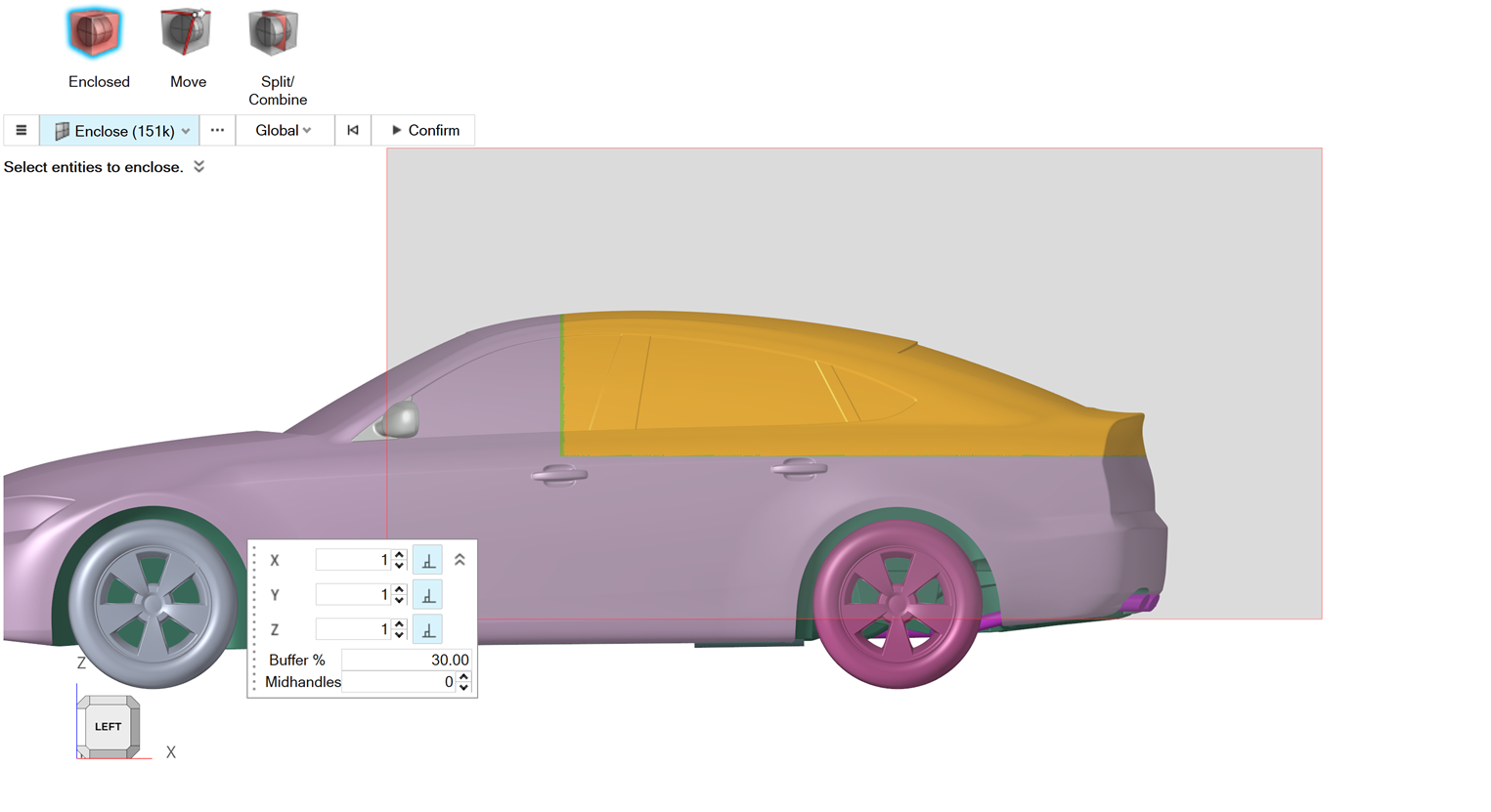
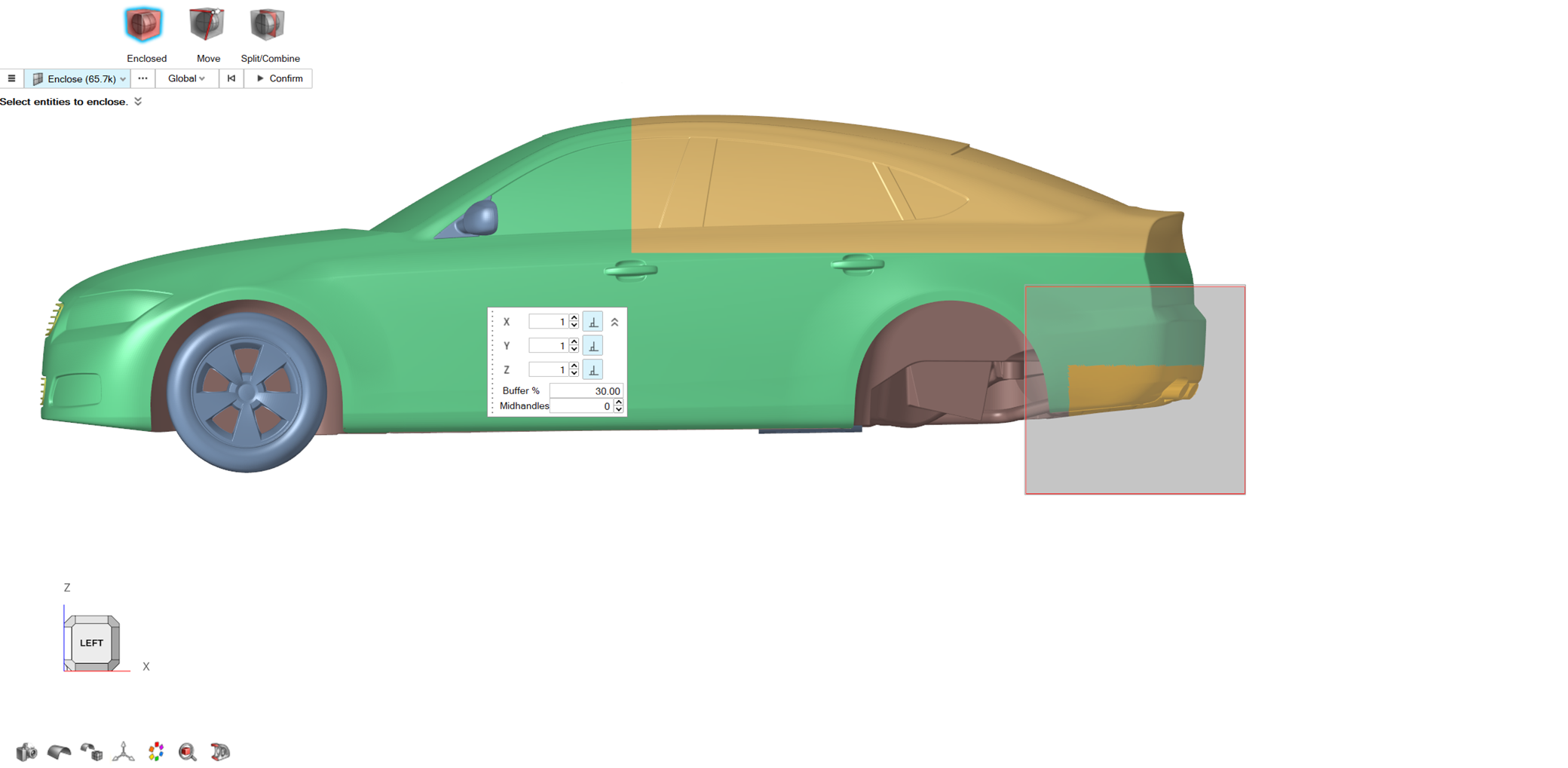
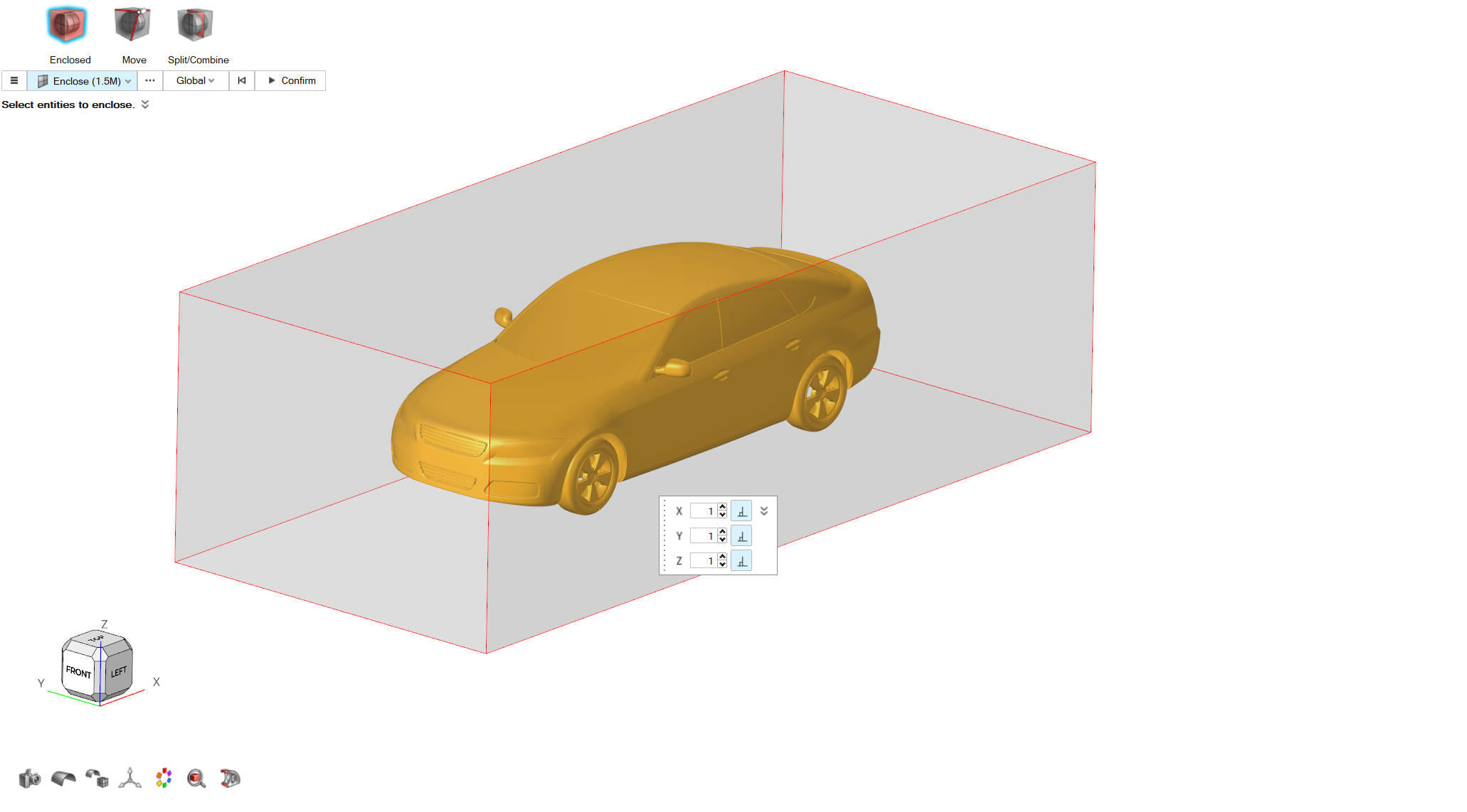
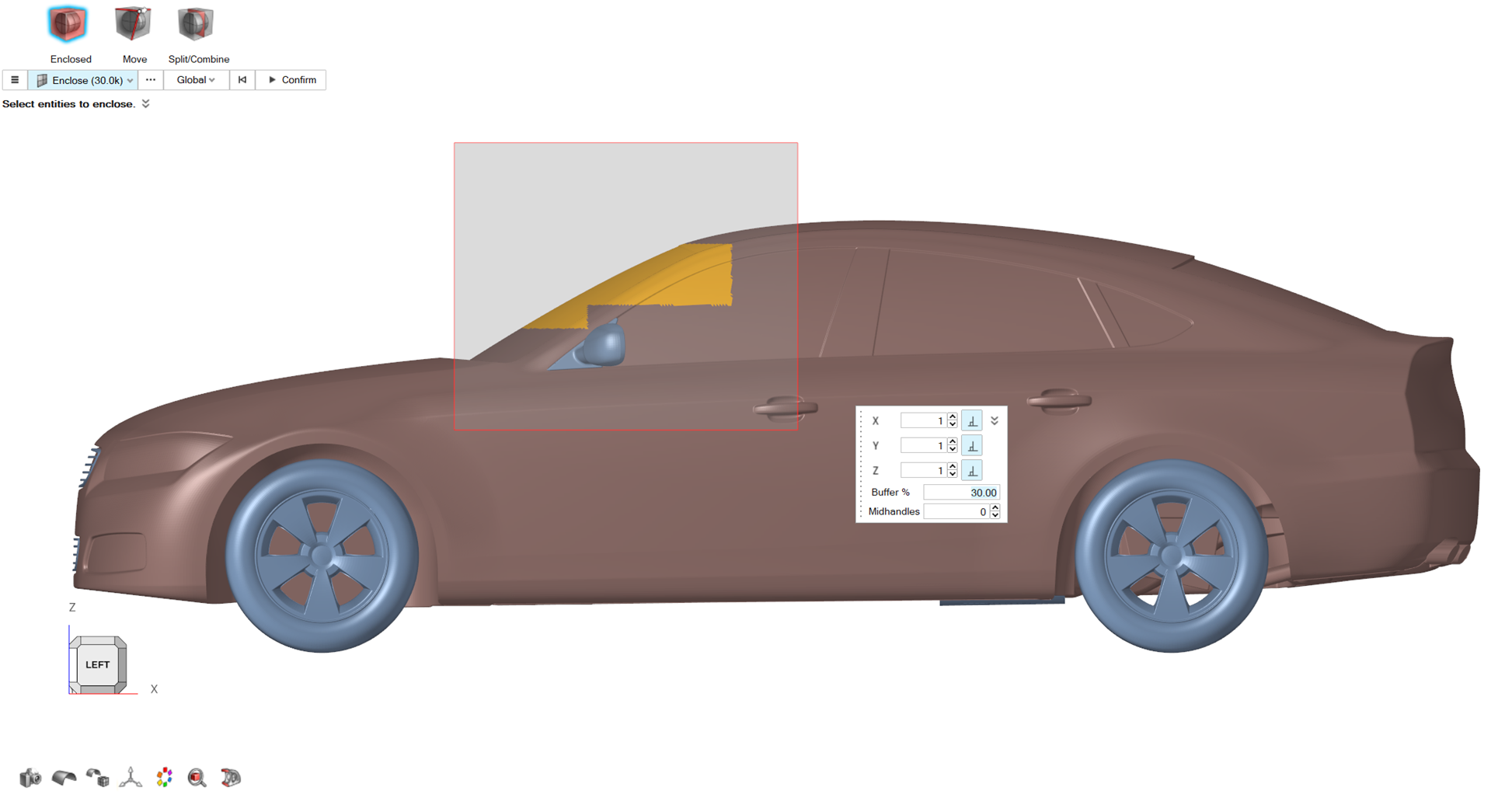
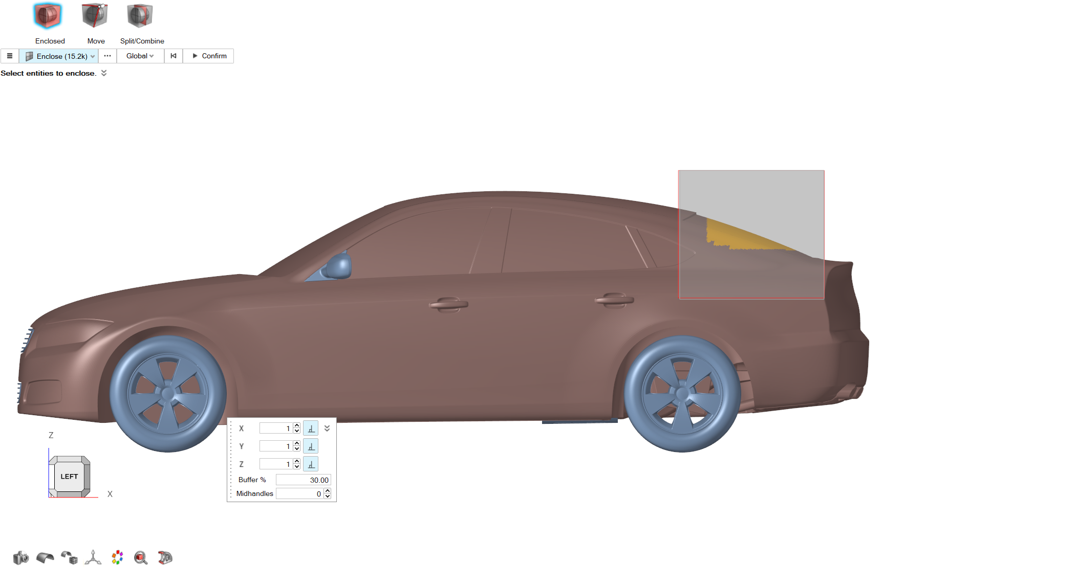
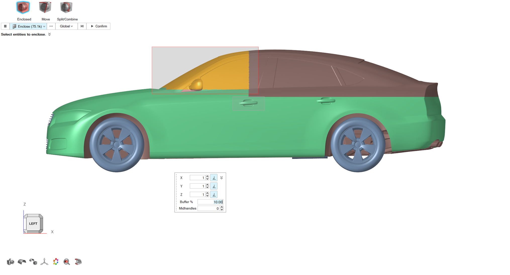
From the secondary toolset, click on the Enclosed
tool.
Figure 3.
From the graphics area, select the elements of the model as shown in the
following picture.
Figure 4.
For Buffer %, set a value of
30.
Click on Confirm to create the control volume.
Control Points
From the Morphing ribbon, Setup
group, click the Control Points tool.
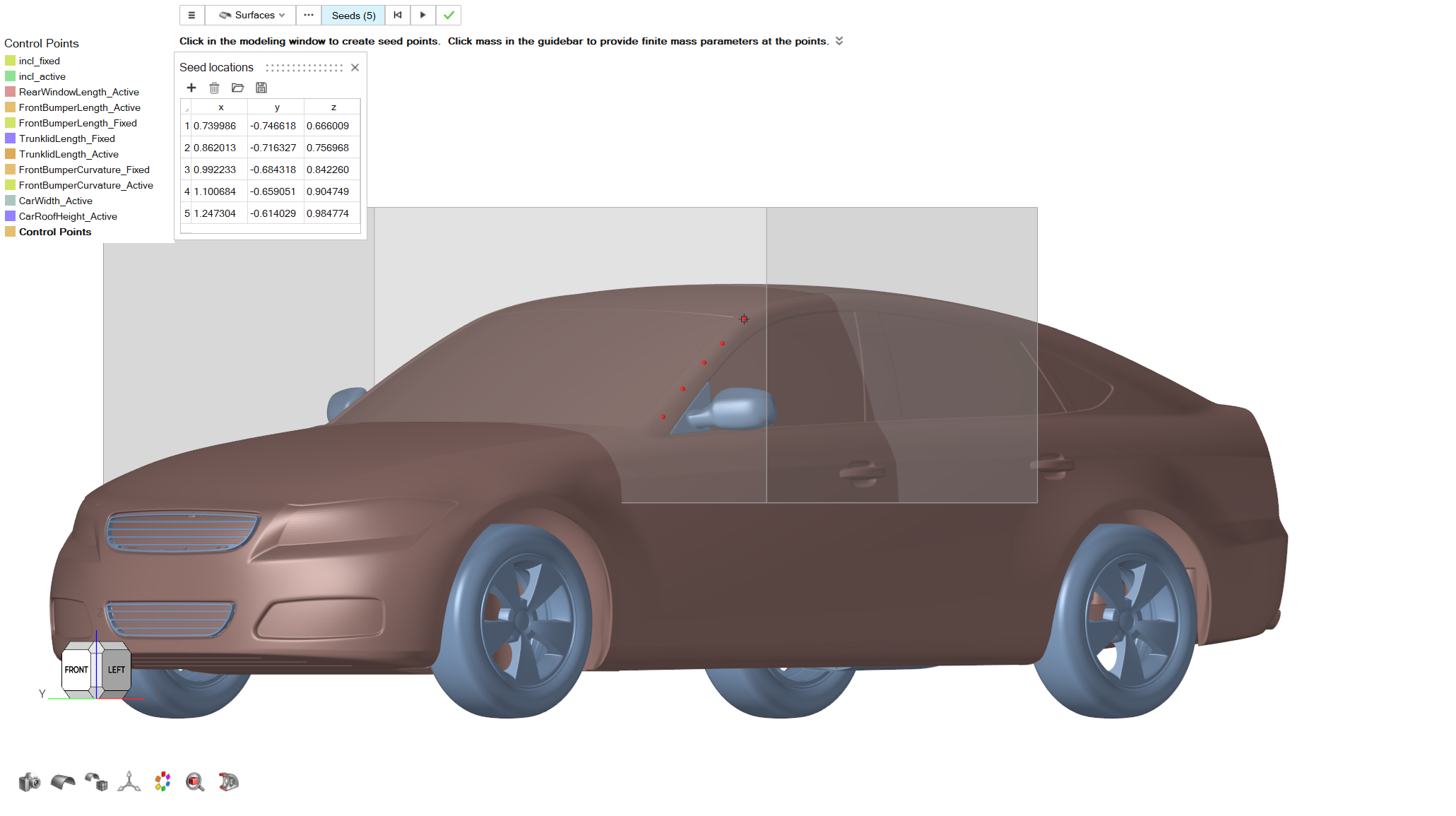
Figure 5.
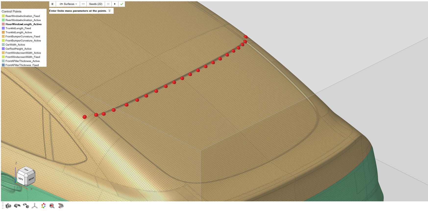
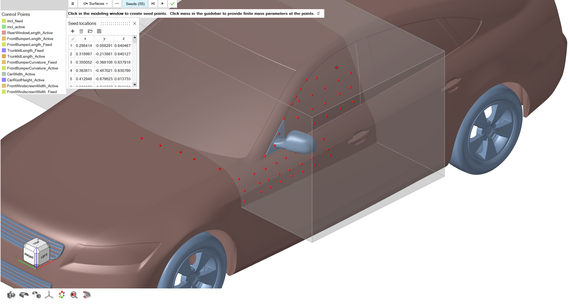
On the guidebar select Seeds and create the following control points on the
model.
Figure 6.
From the Control Points menu, right click on the newly
created control points and rename them to
RearWindowLength_Active.
Morph
From the Morphing ribbon, Setup
group, click on the Morph tool.
Figure 7.
From the guidebar, select Parts, and then select
RearEnd_Fastback part.
From the guidebar, select MorphVolumes, and in the
graphics area select the control volume created on Step 5.
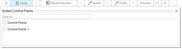
Click on Active on the guidebar.
Click on the three dots button next to Active on the guidebar.
Figure 8.
The Advanced Selection dialog opens.
From the dialog, select RearWindowLength_Active control
point set, and then close the dialog.
For the Translation Vector, set a value of
-0.1 for X direction and a
0.03 for Z direction.
Keep the default value of 0.1 for Impact
Radius.
Note: Attention is required while selecting the Active
control points of the morph and their corresponding Impact Radius. Keep the
whole area of interest in the effective area of these points (this will be
clear later when we visualize the resulting shape).
From the guidebar, click on the Preview button. Examine
the resulting morphed geometry.
If the shape describes the desired geometry changes, click on the
Play button to create the shape.
From the Morph Shape menu, right click on the created shape and rename it to
RearWindowLength.
Figure 9.
Click on the green checkmark to exit the tool.
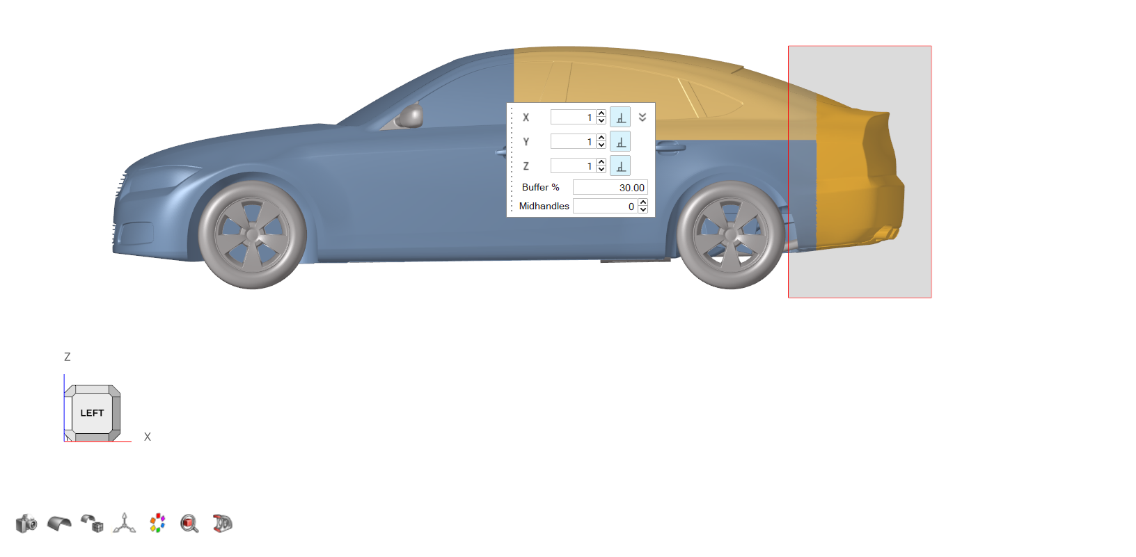
Front Bumper Length
Control Volume
From the Morphing ribbon, Setup
group, click the Volumes tool, and from the secondary
tool select Enclosed tool.
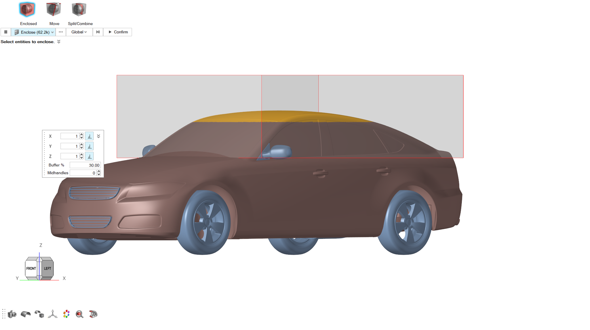
From the graphics area, select the elements of the model as shown in the
following picture.
Figure 10.
For Buffer% keep a value of
30.
Click on the Confirm button to create the control
volume.
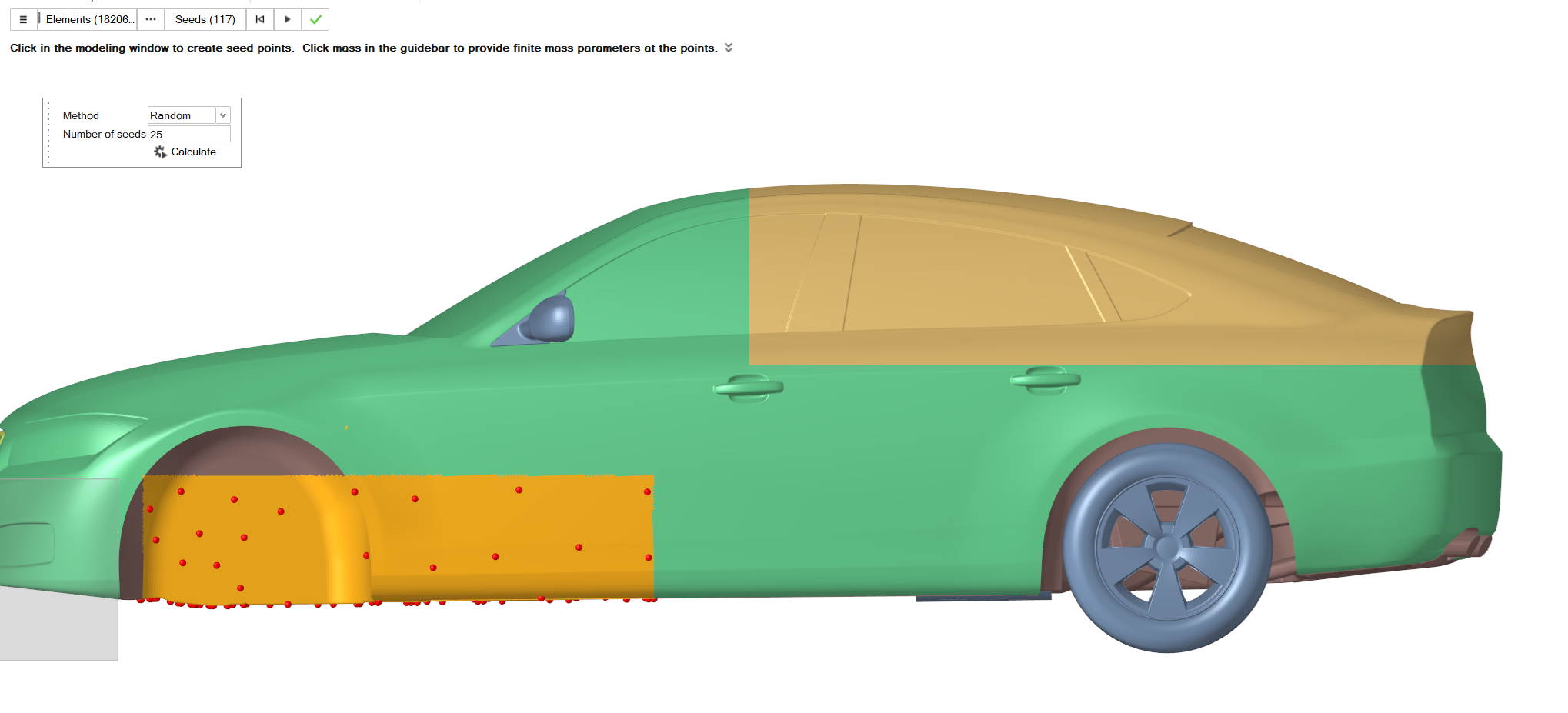
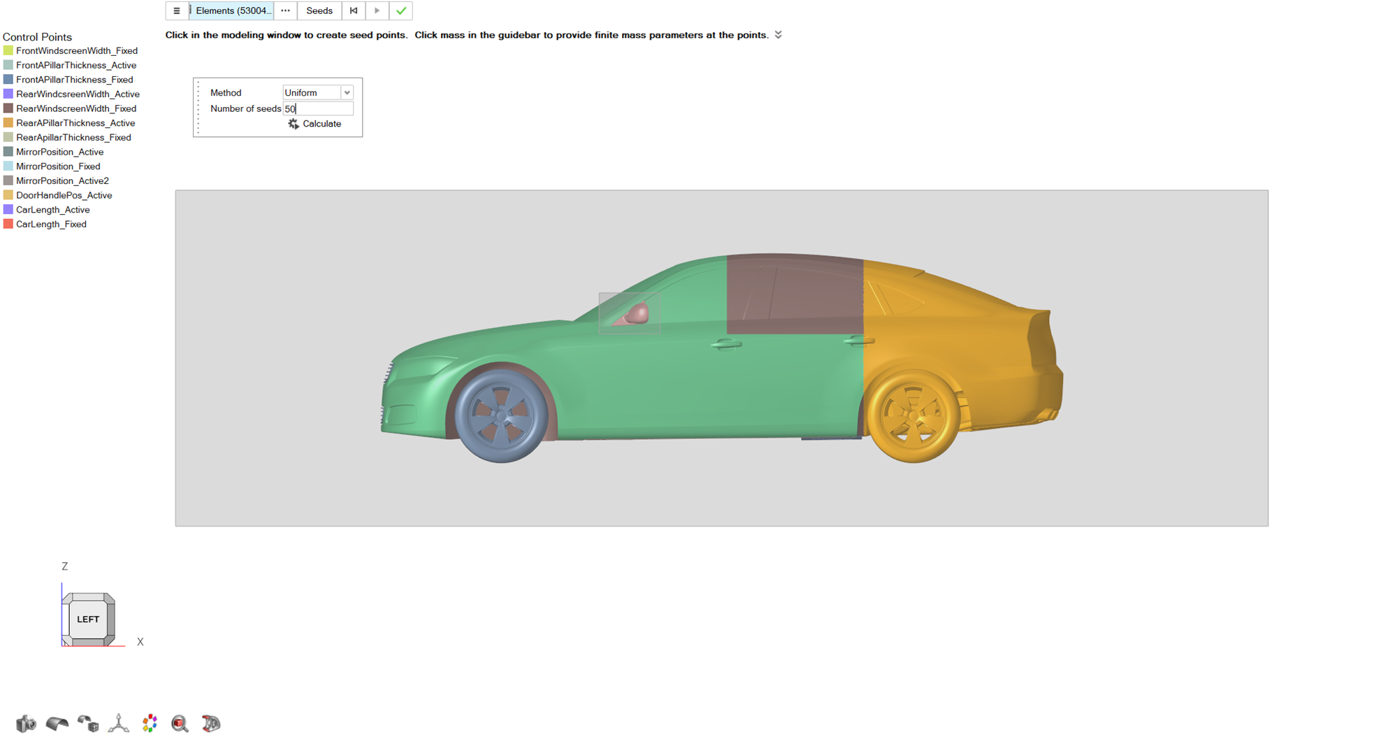
Control Points
From the Morphing ribbon, Setup
group, click the Control Points tool.
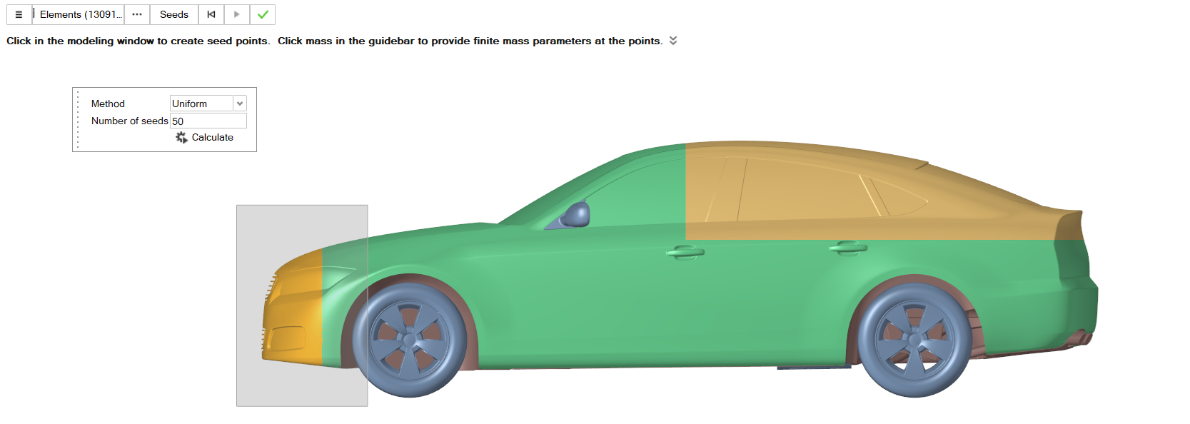
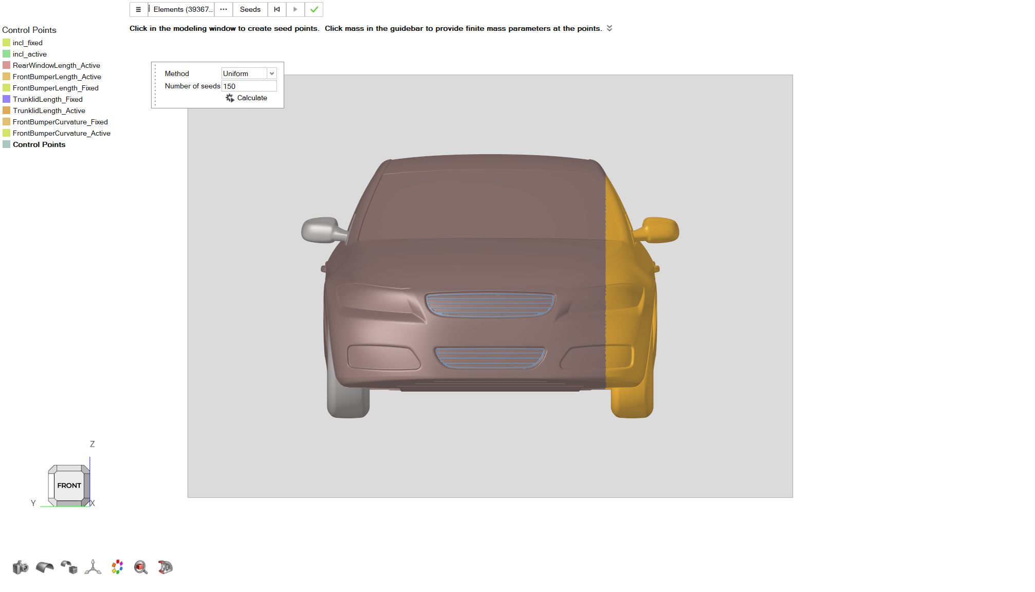
From the guidebar, set the Selection to
Elements. A dialog pops up. Select Uniform
Method and set Number of Seeds to
50.
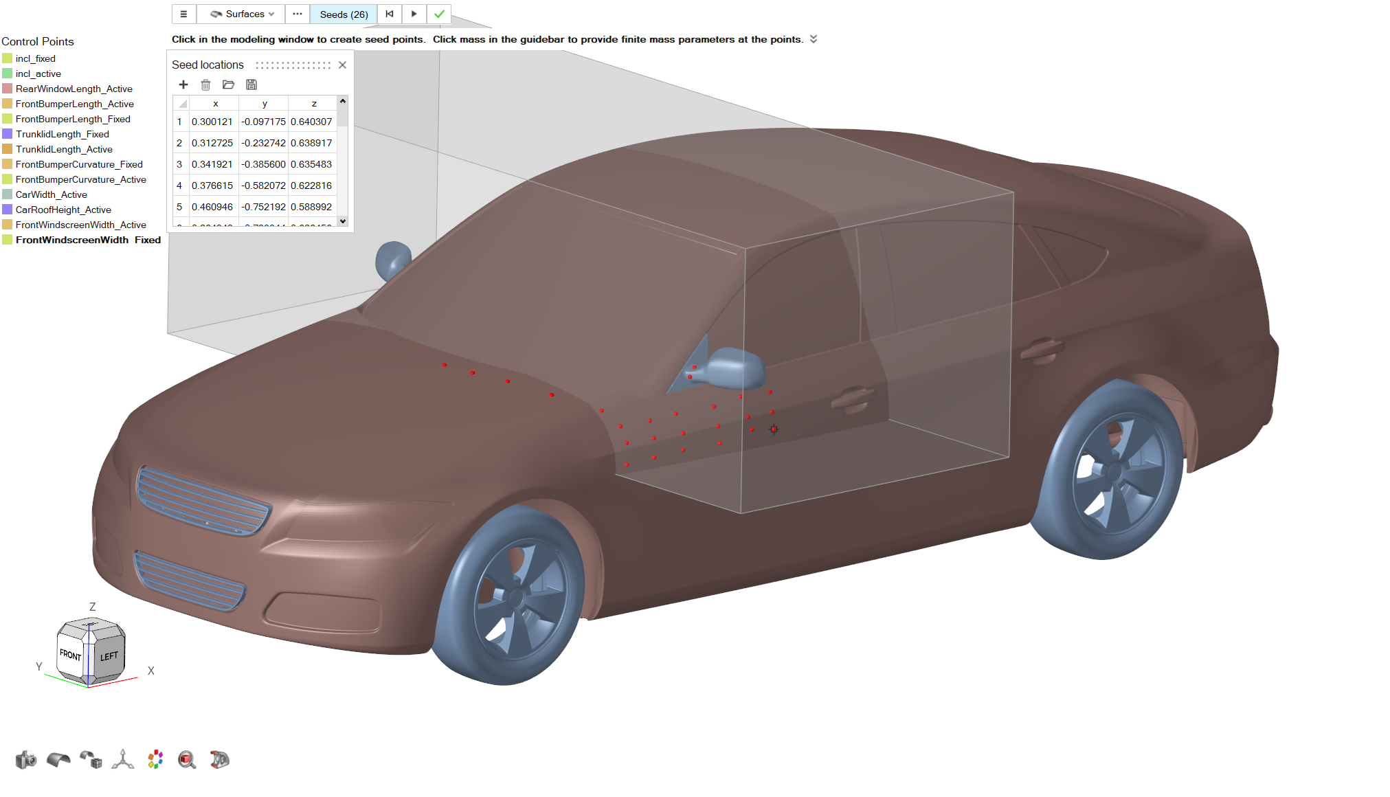
From the graphics area, select the elements on the front side of the model as
shown in the following picture.
Figure 11.
Click on the Calculate button to create the control
points.
Click on the Play button to create the control points
set. From the Control Points menu, right click on the newly
created control points and Rename the set to
FrontBumperLength_Active.
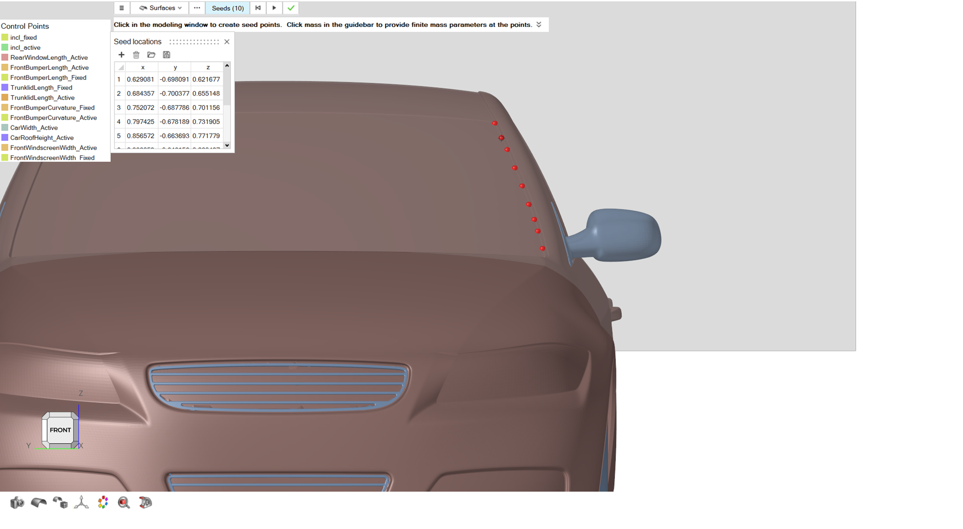
Repeat Steps 1-5 to create the control points shown in the
following picture. From the Control Points menu, right
click on the newly created control points and Rename the
set to FrontBumperLength_Fixed.
Figure 12.
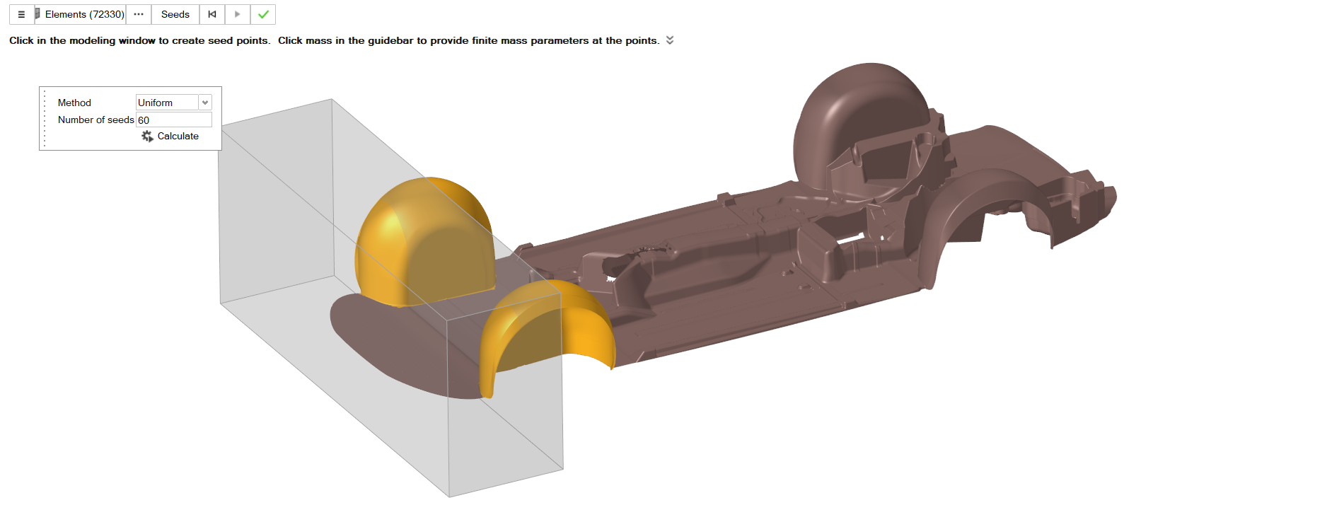
Optional: Alternatively, to make sure wheelwells are properly described by the control
points, isolateUnderbody part from the Part Browser.
From Control Points tool guidebar, set the selection to Elements, and select
from the graphics area the elements that correspond to the wheelwells. Select
Uniform method and a value of
60 to 80 for Number
of seeds. Click on the Calculate button to create these control
points. Then from the Part Browser, proceed to Show All
the parts and then continue to place the rest of the displayed Fixed
points.
Figure 13.
Morph
From the Morphing ribbon, Setup
group, click the Morph tool.
From the guidebar, click on Parts and select
10_grill, Underbody, Body parts.
From the guidebar, select MorphVolumes, and in the
graphics area select the control volume created on Step 4.
Click on Active on the guidebar.
Click on the three dots button next to Active on the guidebar.
From the dialog, select FrontBumperLength_Active control
point set, and then close the dialog.
Click on Fixed on the guidebar.
Click on the three dots button next to Fixed on the
guidebar.
The Advanced Selection dialog opens.
From the dialog, select FrontBumperLength_Fixed control
point set, and then close the dialog.
For the Translation Vector, set a value of
-0.15 for X direction.
Set a value of 0.5 for Impact Radius.
From the guidebar, click on the Preview button. Examine
the resulting morphed geometry.
If the shape describes the desired geometry changes, click on the
Play button to create the shape.
From the Morph Shape menu, right click on the created shape and rename the new
shape as FrontBumperLength. Click on the green checkmark
to exit the tool.
Ramp Angle
Control Volume
From the Morphing ribbon, Setup
group, click the Volumes tool, and from the secondary
tool select Enclosed tool.
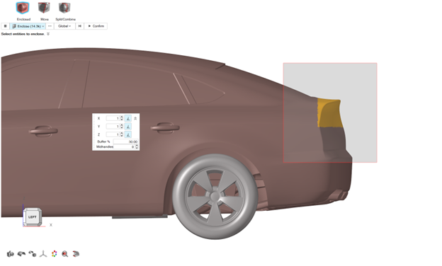
From the graphics area select the elements of the model as shown in the
following picture.
For Buffer% keep a value of
30.
Click on the Confirm button to create the control
volume.
Figure 14.
Control Points
From the Morphing ribbon, Setup group, click the Control Points tool. Select
the Seeds option.
Place control points in the front area of the model as shown in the following
picture.
Figure 15.
Click on the Play button to create the control points set. From the Control
Points menu, right click on the newly created control points and Rename the set
to RampAngle_Active.
From the Morphing ribbon, Setup group, click the Control Points tool.
From the guidebar, set the Selection to
Elements. A dialog pops up. Select Uniform
Method and set Number of Seeds to
100.
Click on the Calculate button. Click on the
Play button to create the control points set. From
the Control Points menu, right click on the newly created control points and
Rename the set to
RampAngle_Fixed.
Figure 16.
Morph
From the Morphing ribbon, Setup group, click the
Morph tool.
From the guidebar, click on Parts and select
Underbody, 10_grill,
Body parts.
From the guidebar, click on the MorphVolumes and in the
graphics area select the volume created on Step 4.
Click on Active, then click on the three dots button
next to it on the guidebar. From the Advanced Selection
dialog select RampAngle_Active and close the
dialog.
Click on Fixed, then click on the three dots button next
to it on the guidebar. From the Advanced Selection dialog select
RampAngle_Fixed and close the dialog.
For the Translation Vector, set a value of
0.04 for Z direction.
For Impact Radius, set a value of
1. Keep the Uniform option for
Impact Radius type.
From the guidebar, click on the Preview button, examine
the morphed geometry and then click on the Play button to
create the shape.
From the Morph Shape menu, right click on the new shape and
Rename it as RampAngle. Click
on the green checkmark to exit the tool.
Trunklid Length
Control Volume
From the Morphing ribbon, Setup
group, click the Volumes tool, and from the secondary
tool select the Enclosed tool.
From the graphics area, select the elements of the model as shown in the
following picture.
For Buffer% retain a value of
30.
Click Confirm to create the control volume.
Figure 17.
Control Points
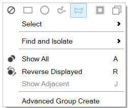
Exit any open tool and right click anywhere in the graphics area. From the
right click dialog, click the Polyline button.
Figure 18.
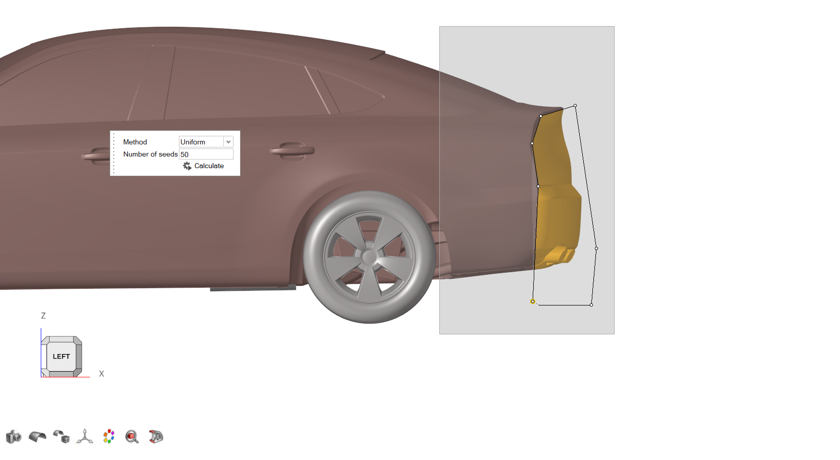
From the Morphing ribbon, Setup
group, click the Control Points tool.
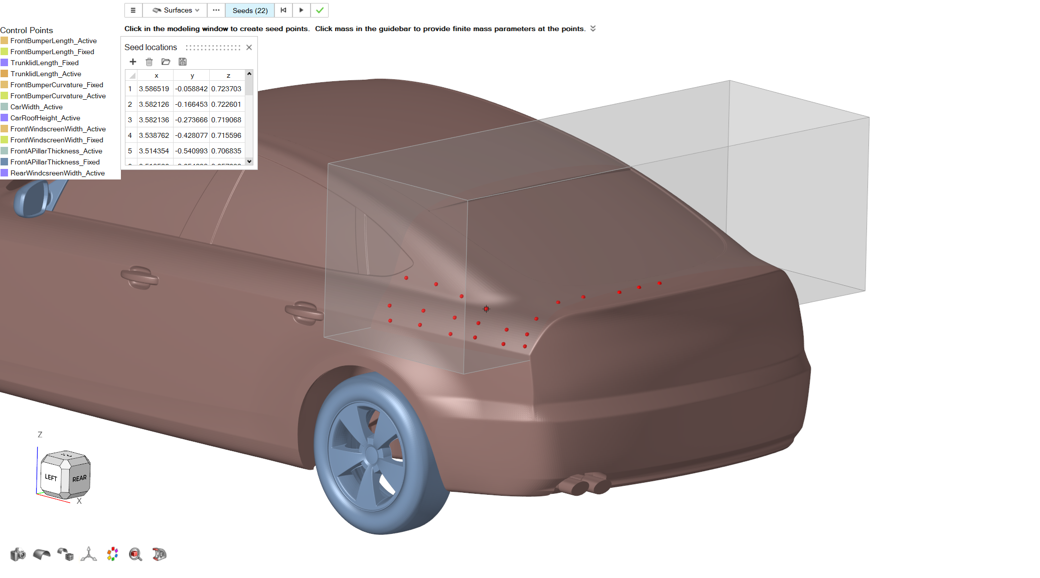
From the guidebar, set the Selection to Elements. A dialog pops up. Select
Uniform Method and set Number of
Seeds to 50.
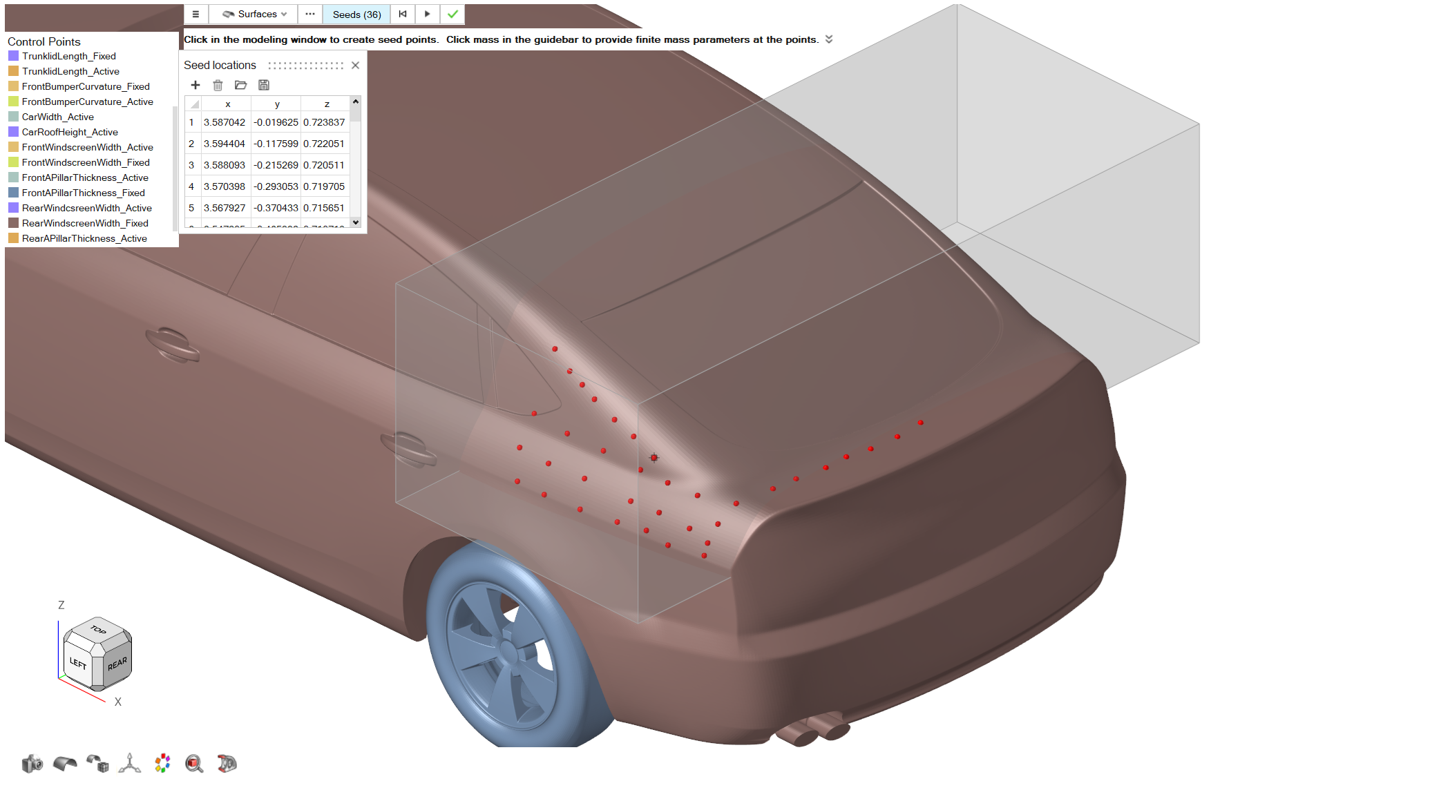
From the graphics area select the elements on the rear side of the model as
shown in the following picture.
Figure 19.
Click on the Calculate button. Review the seeds location and then click on the
Play button to create the control points set.
From the Control Points menu, right click on the new control points set and
rename as
TrunklidLength_Active.
Repeat Step 1 to return to Box Select.
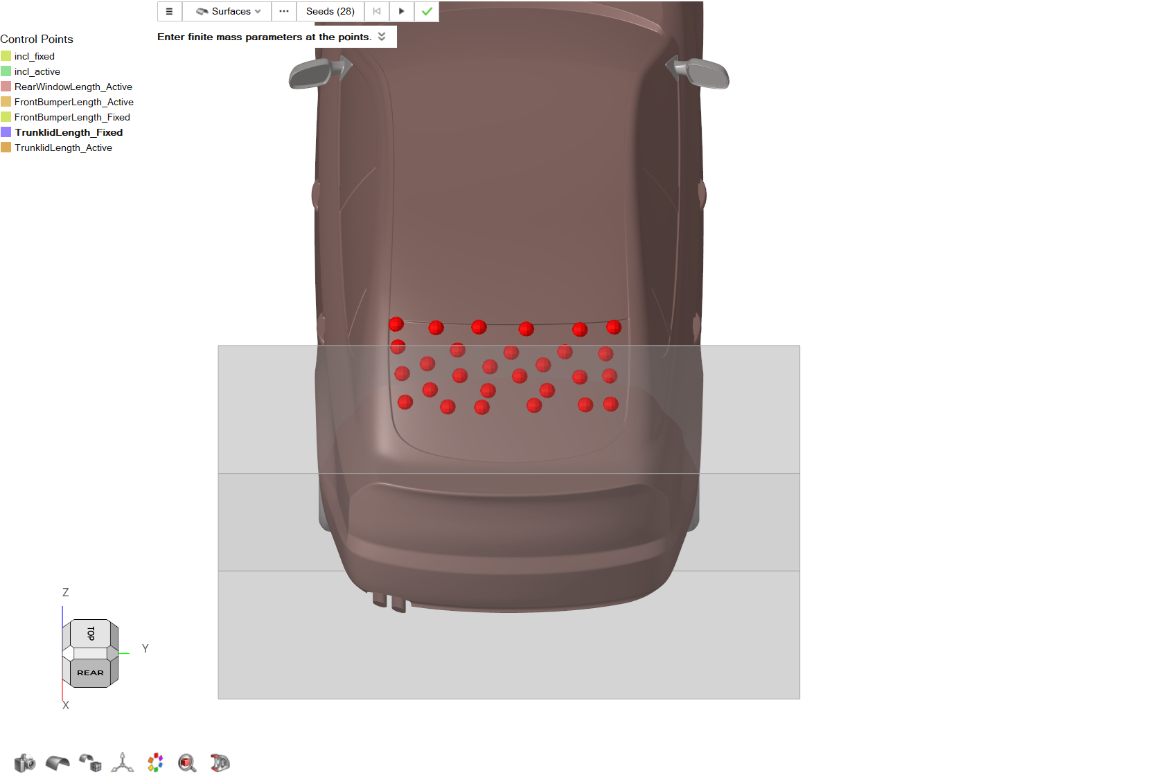
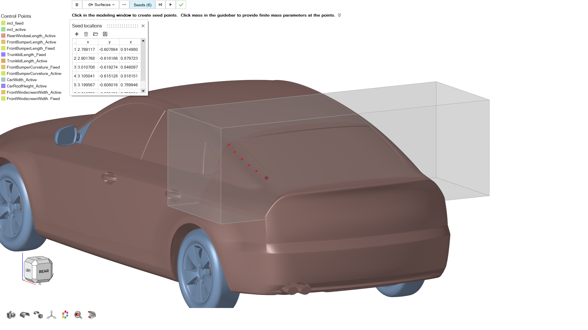
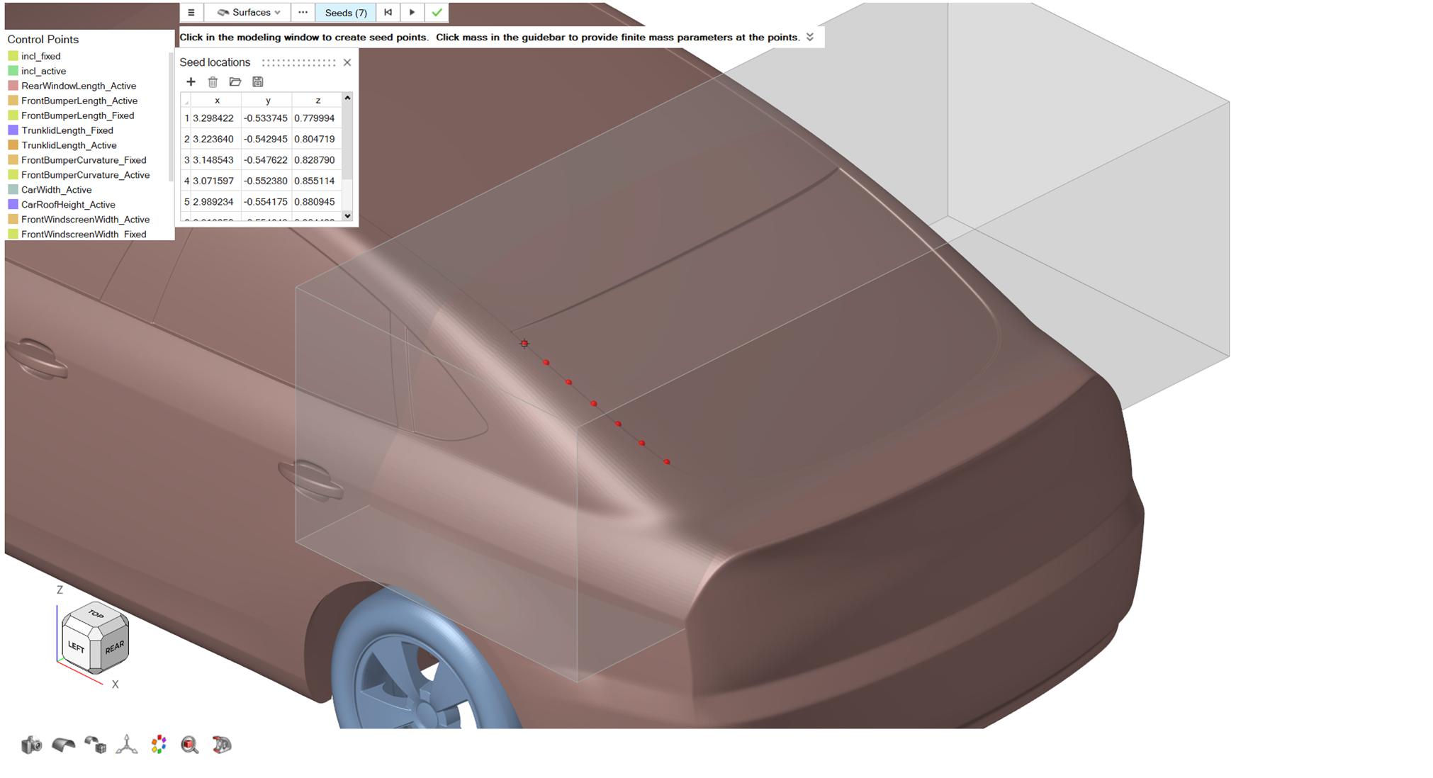
Click on the Control Points tool, then click on Seeds and create the following
control points on the rear windshield of the model.
Figure 20.
Click on the Play button to create the set, and from the
Control Points menu right click and
rename it as
TrunklidLength_Fixed.
Morph
From the Morphing ribbon, Setup group, click the Morph
tool.
From the guidebar, click on Parts and select
Underbody, RearEnd_FastBack, ExhaustSystem, Body
parts.
From the guidebar click on the MorphVolumes and in the
graphics area select the volume created on Step 4.
Click on Active, then click on the three dots button
next to it on the guidebar. From the Advanced Selection dialog, select
TrunklidLength_Active and close the dialog.
Click on Fixed, then click on the three dots button next
to it on the guidebar. From the Advanced Selection dialog, select
TrunklidLength_Fixed and close the dialog.
For the Translation Vector, set a value of
0.15 for X direction.
For Impact Radius, use a value of
0.5. Keep the Uniform option
for Impact Radius type.
From the guidebar, click on the Preview button, examine
the morphed geometry and then click on the Play button to
create the shape.
From the Morph Shape menu right click on the new shape and
Rename it as TrunklidLength.
Click on the green checkmark to exit the tool.
Diffusor Angle
Control Volume
From the Morphing ribbon, Setup
group, click the Volumes tool, and from the secondary
tool select Enclosed tool.
From the graphics area select the elements of the model as shown in the
following picture.
For Buffer% set a value of
30.
Click on Confirm to create the control volume.
Figure 21.
Morph
From the Morphing ribbon, Setup
group, click the Morph tool.
From the guidebar, click on the Parts and select
Underbody, Body,
ExhaustSystem parts.
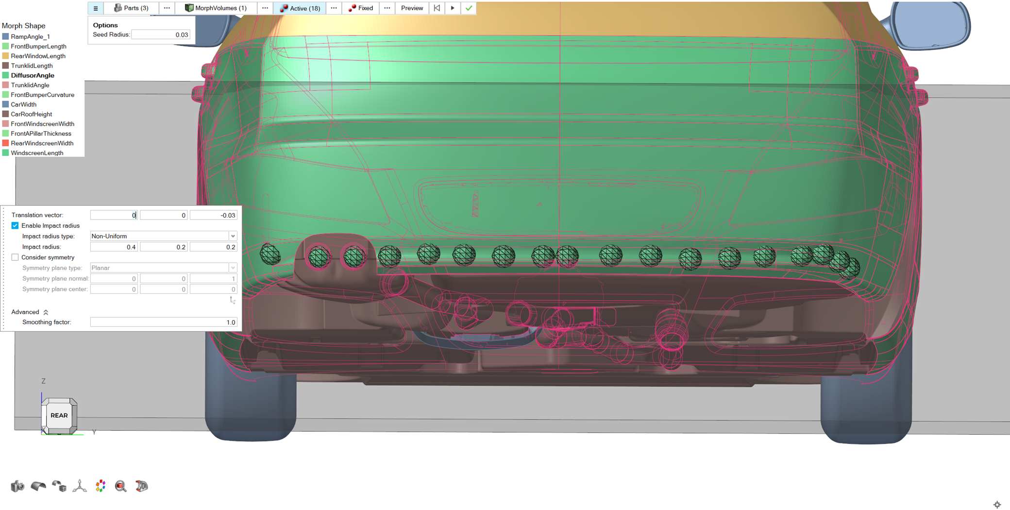
From the guidebar, click on the Morph Volumes and in
graphics select the volume created on Step 4.
From the guidebar click on Active and create the
following control points on the model.
Figure 22.
For the Translation Vector set a value of
-0.03 on Z direction.
For Impact Radius set Non-Uniform
type and a value of (0.4, 0.2, 0.2).
Set a value of 1 for Smoothing
factor.
From the guidebar, click on Preview button, examine the morphed geometry and
then click on the Play button to create the new
shape.
From the Morph Shape menu, right click on the new shape
and Rename it as DiffusorAngle.
Click on the green checkmark to exit the tool.
Trunklid Angle
Control Volume
From the Morphing ribbon, Setup
group, click the Volumes tool, and from the secondary
tool select Enclosed tool.
From the graphics area, select the elements of the model as shown in the
following picture.
Figure 23.
For Buffer% keep a value of
30.
Click on the Confirm button to create the control
volume.
Morph
From the Morphing ribbon, Setup
group, click the Morph tool.
From the guidebar, click on Parts. Select
RearEnd_Fastback, Body.
From the guidebar, click on MorphVolumes and in the
graphics area select the control volume created on Step 4.
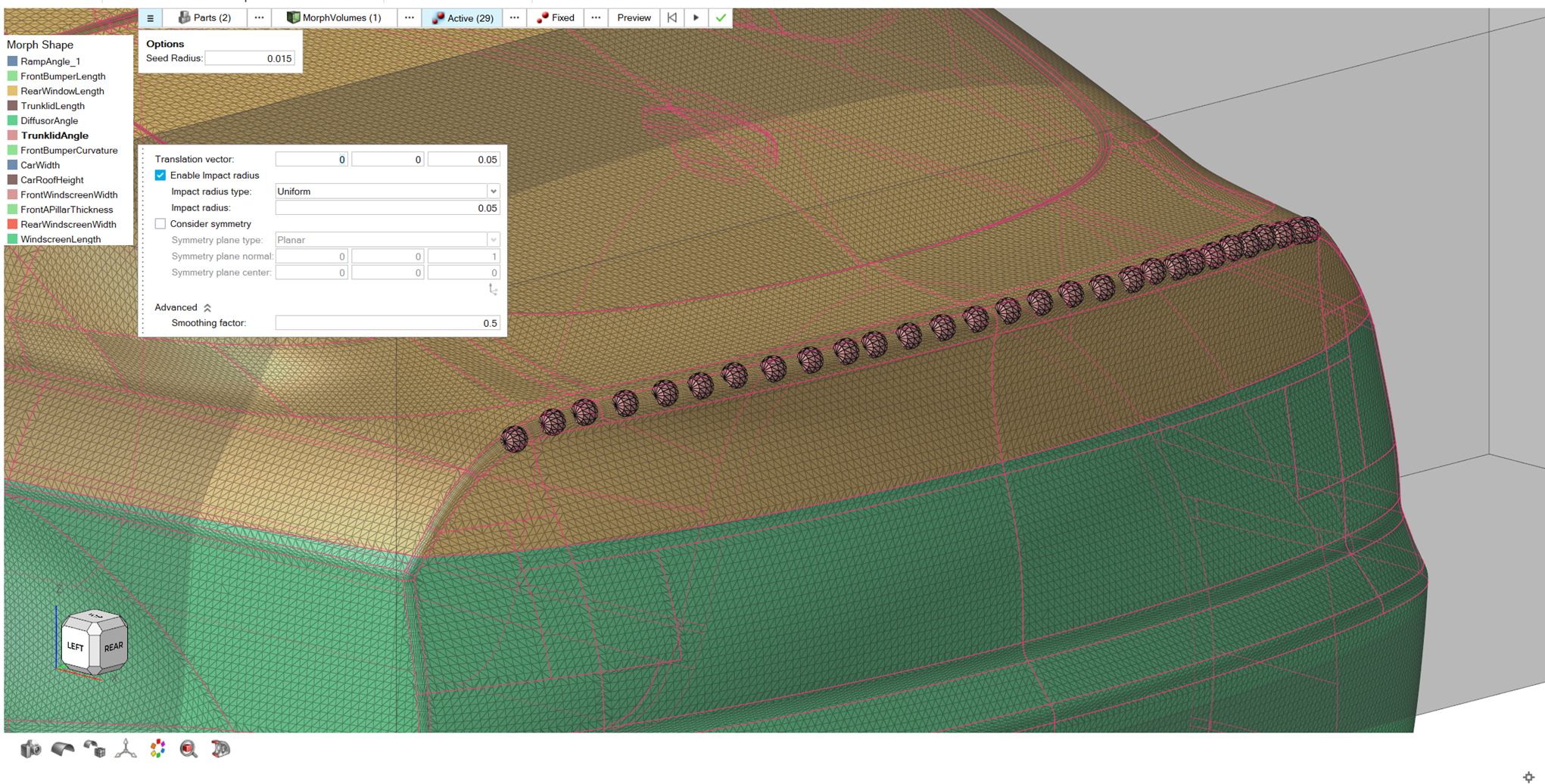
Click on Active on the guidebar. In the graphics area,
create the following control points.
Figure 24.
For the Translation Vector, set a value of
0.05 in Z direction.
Set a value of 0.05 for Impact Radius.
From the guidebar, click on the Preview button. Examine
the morphed geometry and then click on the Play button to
create the shape.
From the Morph Shape menu, right click on the created shape and rename the new
shape as TrunklidAngle. Click on the green checkmark to
exit the tool.
Front Bumper Curvature
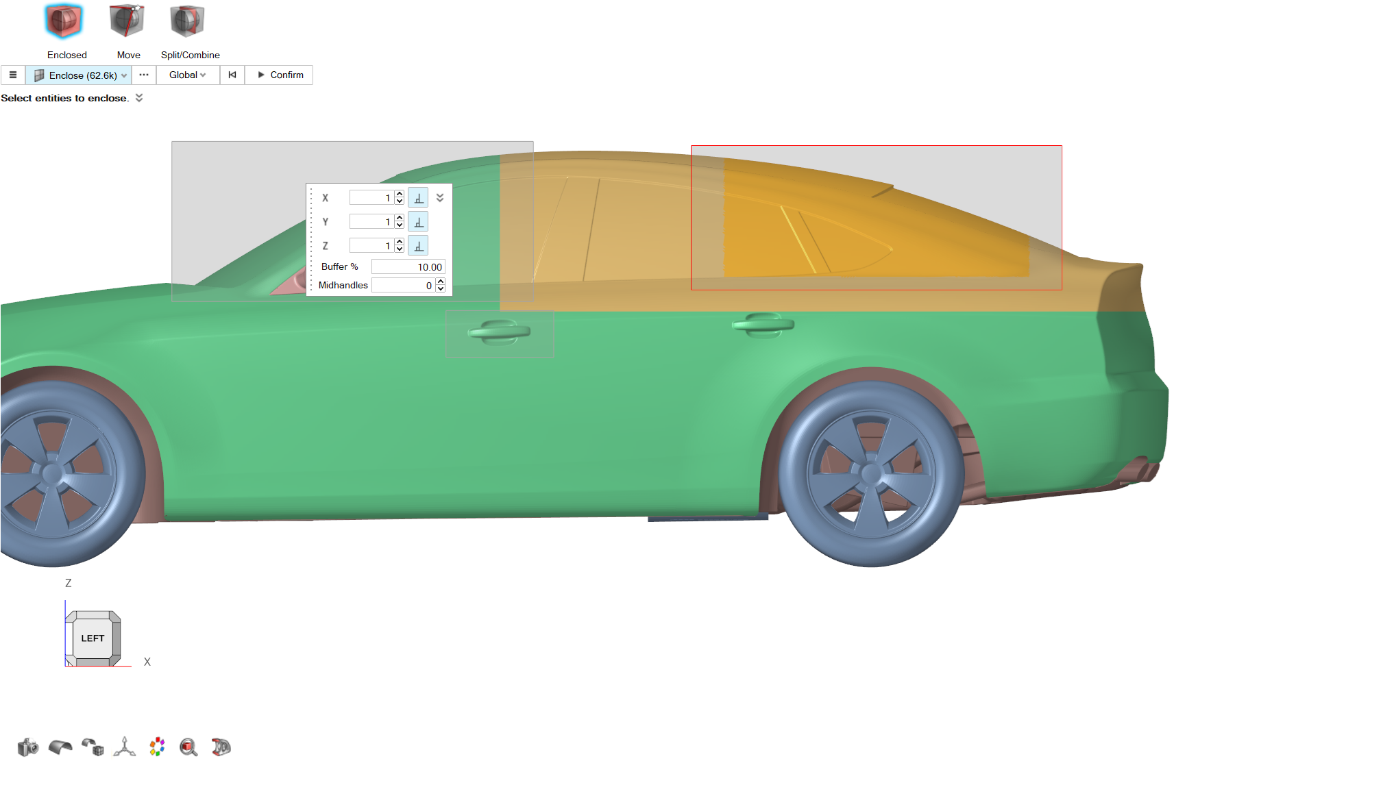
Control Volume
From the Morphing ribbon, Setup
group, click the Volumes tool, and from the secondary
tool select Enclosed tool.
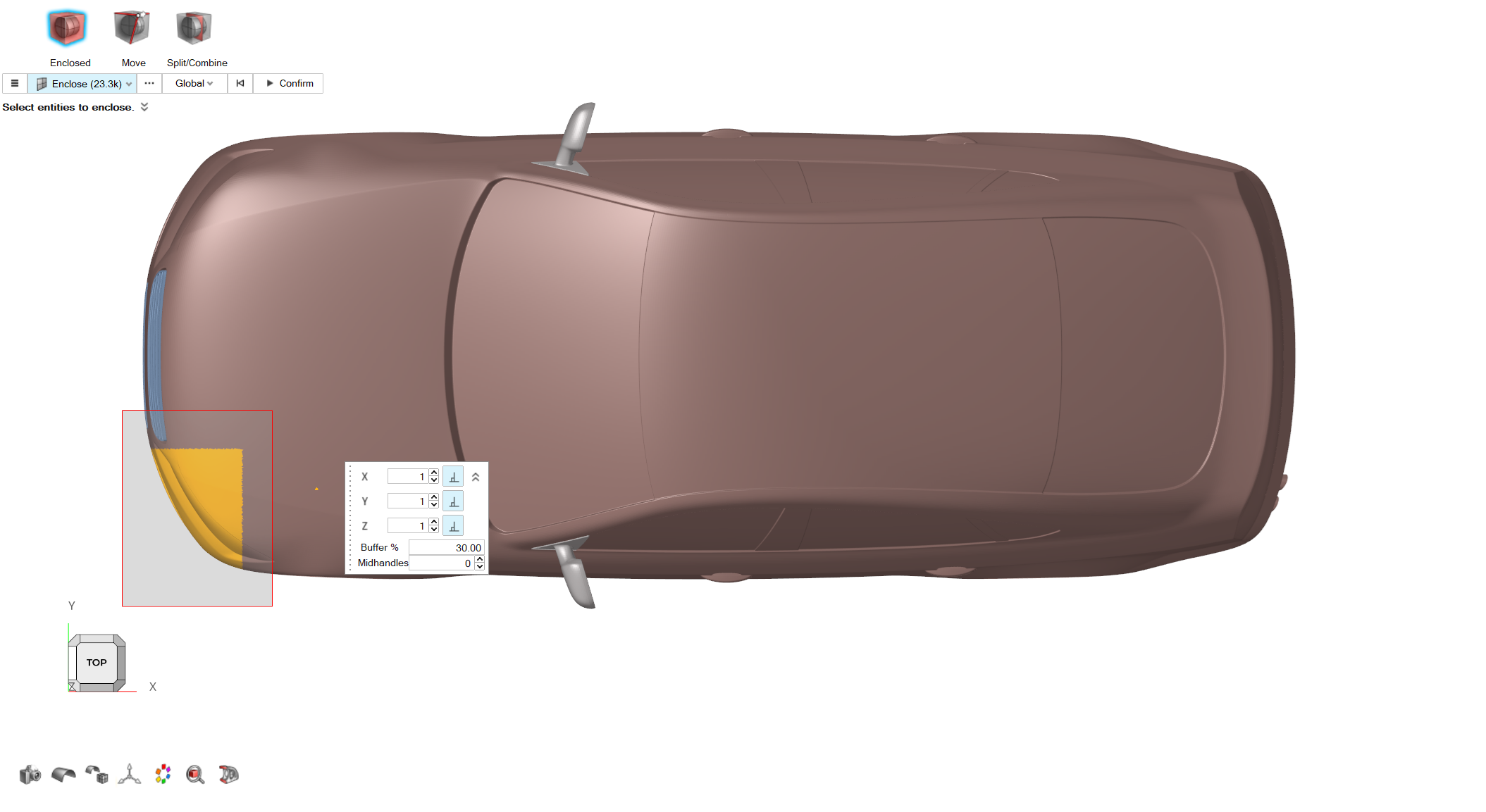
From the graphics area, select the elements on the front end of the model as
shown in the following picture.
Figure 25.
For Buffer% keep a value of
30.
Click on the Confirm button to create the control
volume.
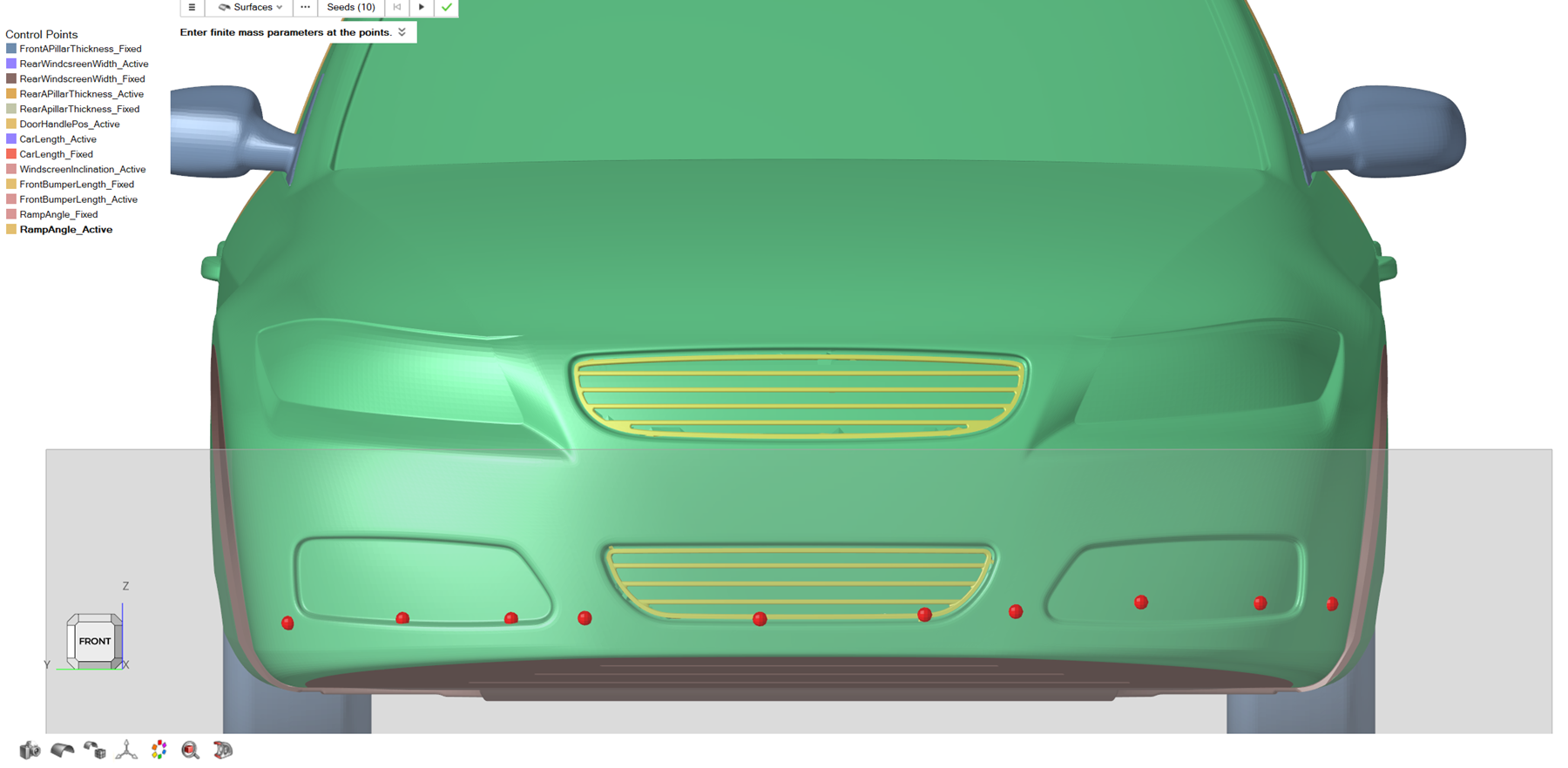
Control Points
From the Morphing ribbon, Setup
group, click the Control Points tool. Select the
Seeds option.
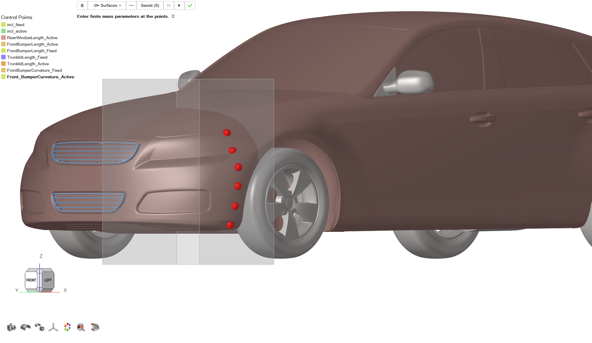
Place the following control points on the model, as shown in the following
picture.
Figure 26.
Click on the Play button to create the control points
set. From the Control Points menu, right click on the newly
created control points and Rename the set to
FrontBumperCurvature_Active.
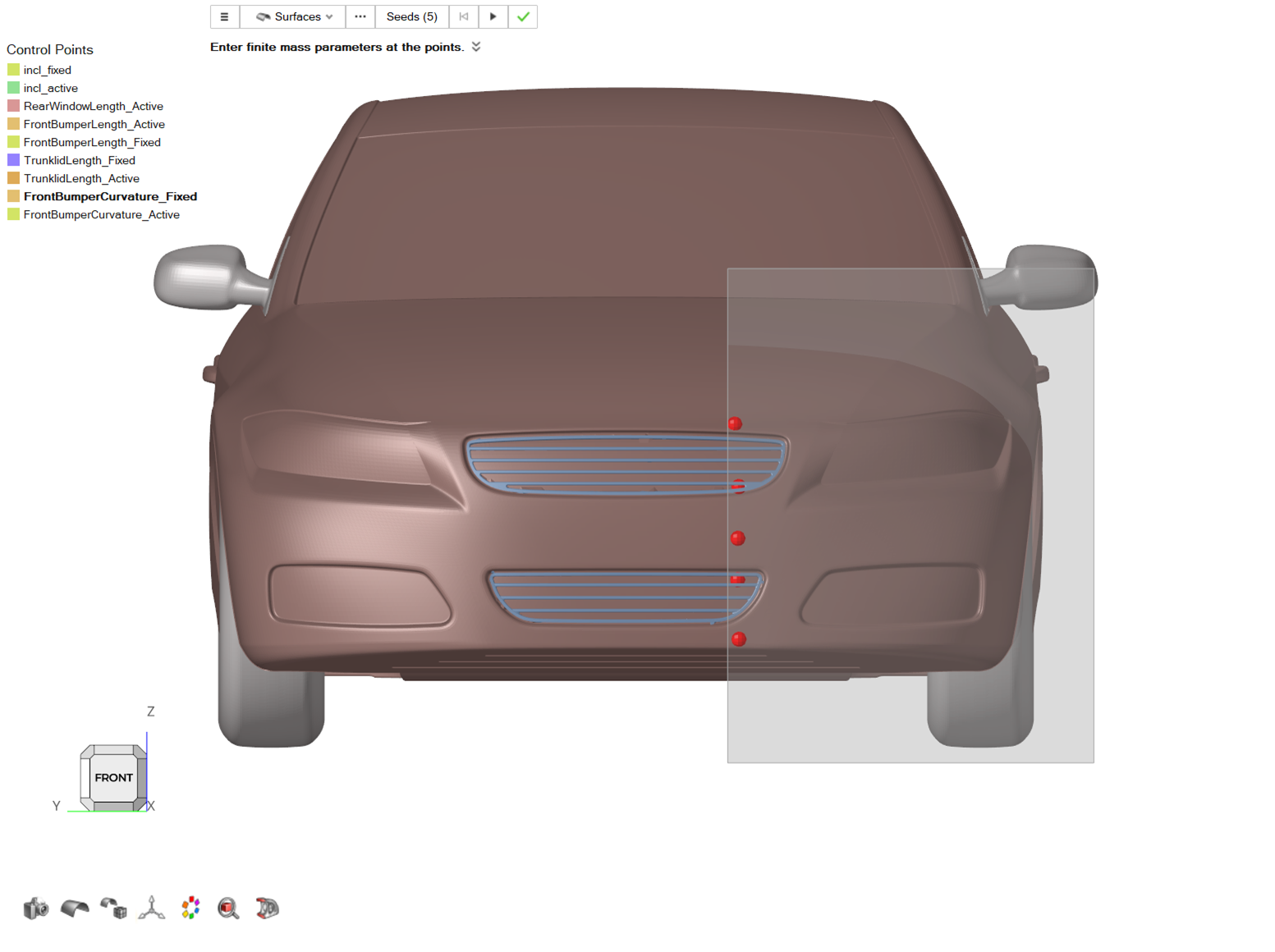
Repeat Steps 1-3 and create the control points shown in the
following picture. From the Control Points menu, right
click on the newly created control points and Rename the
set to FrontBumperCurvature_Fixed.
Figure 27.
Morph
From the Morphing ribbon, Setup
group, click the Morph tool.
From the guidebar, click on Parts and select
10_grill, Underbody, Body parts.
From the guidebar, select MorphVolumes, and in the
graphics area select the control volume created on Step 4.
Click on Active on the guidebar.
Click on the three dots button next to Active on the guidebar. The Advanced
Selection dialog opens. From the list, select
FrontBumperCurvature_Active and close the
dialog.
Click on Fixed on the guidebar. Click on the three dots
button next to Fixed on the guidebar. The Advanced Selection dialog opens. From
the list, select FrontBumperCurvature_Fixed and close the
dialog.
For the Translation Vector, set a value of
-0.15 for X direction.
Set a value of 0.2 for Impact
Radius.
Enable the Consider Symmetry
option. Set Symmetry plane normal as (0, -1,
0).
From the guidebar click on Preview, Examine the morphed geometry and then click
on the Play button to create the shape.
From the Morph Shape menu, right click on the created
shape and rename the new shape as FrontBumperCurvature.
Click on the green checkmark to exit the tool.
Note: For this morph, Active control points were set on
the outer side of the control volume to make an X direction translation that
will affect the desired angle for Front Bumper Curvature. An alternative way
of work is to select the control points set near the grill as the Active
control points and create a morph by setting a Y direction translation to
achieve a similar result (but keeping a different side of the model as
fixed).
Car Width
Control Volume
From the Morphing ribbon, Setup
group, click the Volumes tool, and from the secondary
tool select Enclosed tool.
From the graphics area, select all the elements of the model.
Figure 28.
Click Confirm to create the control volume.
Control Points
From the Morphing ribbon, Setup
group, click the Control Points tool.
From the guidebar, set the Selection to Elements. A dialog pops up. Select
Uniform Method and set Number of
Seeds to 150.
From the graphics area, select the elements on the left side of the model as
shown in the following picture.
Click on the Calculate button. Review the seeds location
and then click on the Play button to create the control
points set.
Figure 29.
From the Control Points menu, right click on the newly
created control points and rename the set to
CarWidth_Active.
Morph
From the Morphing ribbon, Setup
group, click the Morph tool.
From the guidebar, click on Parts and select all the
parts in the graphics area.
From the guidebar, select MorphVolumes, and in the
graphics area select the control volume created on Step 3.
Click on Active on the guidebar.
Click on the three dots button next to Active on the guidebar. The Advanced
Selection dialog opens. From the list select CarWidth_Active and close the
dialog.
For the Translation Vector, set a value of
-0.15 for Y direction.
Set a value of 0.5 for Impact
Radius.
Enable the Consider Symmetry option. Set
Symmetry plane normal as (0, -1,
0).
From the guidebar click on Preview. Examine the morphed
geometry and then click on the Play button to create the
shape.
From the Morph Shape menu, right click on the created
shape and rename the new shape as
CarWidth. Click on the green checkmark to exit the
tool.
Car Roof Height
Control Volume
From the Morphing ribbon, Setup
group, click the Volumes tool, and from the secondary
tool select Enclosed tool.
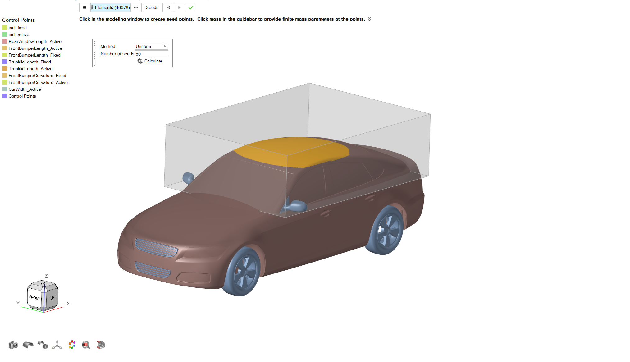
From the graphics area select the elements of the model as shown in the
following picture.
Keep a Buffer% value of 30.
Click on Confirm to create the control volume.
Figure 30.
Control Points
From the Morphing ribbon, Setup
group, click the Control Points tool.
From the guidebar, set the Selection to
Elements. A dialog pops up. Select Uniform
Method and set Number of Seeds to
50.
From the graphics area, select the elements on the left side of the model as
shown in the following picture.
Click on the Calculate button. Review the seeds location
and then click on the Play button to create the control
points set.
Figure 31.
From the Control Points menu, right click on the newly
created control points and rename the set to
CarRoofHeight_Active.
Morph
From the Morphing ribbon, Setup
group, click the Morph tool.
From the guidebar, click on Parts and select
RearEnd_Fastback, Body parts.
From the guidebar, select MorphVolumes, and in the
graphics area select the control volume created on Step 5.
Click on Active on the guidebar.
Click on the three dots button next to Active on the guidebar.
The Advanced Selection dialog opens.
From the dialog, select CarRoofHeight_Active control
point set, and then close the dialog.
For the Translation Vector, set a value of
-0.05 for X direction.
Set a value of 0.5 for Impact
Radius.
From the guidebar, click on the Preview button. Examine
the resulting morphed geometry.
If the shape describes the desired geometry changes, click on the
Play button to create the shape.
From the Morph Shape menu, right click on the created
shape and rename the new shape as CarRoofHeight. Click on
the green checkmark to exit the tool.
Front Windscreen Width
Control Volume
From the Morphing ribbon, Setup
group, click the Volumes tool, and from the secondary
tool select Enclosed tool.
From the graphics area, select the elements of the model as shown in the
following picture.
Figure 32.
Click on Confirm to create the control volume.
Control Points
From the Morphing ribbon, Setup
group, click the Control Points tool. Select the
Seeds option.
Place control points in the front area of the model as shown in the following
picture.
Figure 33.
Click on the Play button to create the control points
set. From the Control Points menu, right click on the newly created control
points and Rename the set to
FrontWindscreenWidth_Active.
Repeat Steps 1-3 to create the control points shown in the
following picture. From the Control Points menu, right
click on the newly created control points and Rename the
set to FrontWindscreenWidth_Fixed.
Figure 34.
Morph
From the Morphing ribbon, Setup
group, click the Morph tool.
From the guidebar, click on Parts and select Body,
RearEnd_Fastback parts.
From the guidebar, select MorphVolumes, and in the
graphics area select the control volume created on Step 3.
Click on Active on the guidebar.
Click on the three dots button next to Active on the guidebar.
The Advanced Selection dialog opens.
From the dialog, select FrontBumperLength_Active control
point set, and then close the dialog.
Click on Fixed on the guidebar.
Click on the three dots button next to Fixed on the guidebar.
The Advanced Selection dialog opens.
From the dialog, select FrontBumperLength_Fixed control
point set, and then close the dialog.
For the Translation Vector, set a value of
0.03 for Y direction.
Set a value of 0.15 for Impact
Radius.
Enable the Consider Symmetry option. Set Symmetry plane
normal as (0, -1, 0).
From the guidebar click on Preview,
Examine the morphed geometry and then click on the
Play button to create the shape.
From the guidebar, click on the Preview button. Examine
the resulting morphed geometry.
If the shape describes the desired geometry changes, click on the
Play button to create the shape.
From the Morph Shape menu, right click on the created
shape and rename the new shape as FrontWindscreenWidth.
Click on the green checkmark to exit the tool.
Front A Pillar Thickness
Control Points
From the Morphing ribbon, Setup
group, click the Control Points tool. Select the
Seeds option.
Place control points in the front area of the model as shown in the following
picture.
Figure 35.
From the Control Points menu, right click on the newly
created control points and Rename the set to
FrontAPillarThickness_Active.
Repeat Steps 1-3 to create the control points shown in the
following picture. From the Control Points menu, right
click on the newly created control points and rename the
set to FrontAPillarThickness_Fixed.
Figure 36.
Morph
From the Morphing ribbon, Setup
group, click the Morph tool.
From the guidebar, click on Parts and select
Body parts.
From the guidebar, select MorphVolumes, and in the
graphics area select the control volume created on Step 3.
Click on Active on the guidebar.
Click on the three dots button next to Active on the guidebar.
The Advanced Selection dialog opens.
From the dialog, select FrontAPillarThickness_Active
control point set, and then close the dialog.
Click on Fixed on the guidebar.
Click on the three dots button next to Fixed on the guidebar.
The Advanced Selection dialog opens.
From the dialog, select FrontAPillarThickness_Fixed
control point set, and then close the dialog.
For the Translation Vector, set a value of
0.03 for Y direction.
Set a value of 0.1 for Impact
Radius.
Enable the Consider Symmetry option. Set
Symmetry plane normal as (0, -1,
0).
From the guidebar, click on Preview. Examine the morphed
geometry and then click on the Play button to create the shape.
From the guidebar, click on the Preview button. Examine
the resulting morphed geometry.
If the shape describes the desired geometry changes, click on the
Play button to create the shape.
From the Morph Shape menu, right click on the created
shape and rename the new shape as FrontAPillarThickness.
Click on the green checkmark to exit the tool.
Rear Windscreen Width
Control Volume
From the Morphing ribbon, Setup
group, click the Volumes tool, and from the secondary
tool select Enclosed tool.
From the graphics area select the elements of the model as shown in the
following picture.
Figure 37.
Click on the Confirm button to create the control
volume.
Control Points
From the Morphing ribbon, Setup
group, click the Control Points tool. Select the Seeds
option.
Place control points in the front area of the model as shown in the following
picture.
Figure 38.
Click on the Play button to create the control points
set. From the Control Points menu, right click on the newly
created control points and rename the set to
RearWindscreenWidth_Active.
Repeat Steps 1-3 to create the control points shown in the
following picture. From the Control Points menu, right click on the newly
created control points and rename the set to
RearWindscreenWidth_Fixed.
Figure 39.
Morph
From the Morphing ribbon, Setup
group, click the Morph tool.
From the guidebar, click on Parts and select
RearEnd_Fastback part.
From the guidebar, select MorphVolumes, and in the
graphics area select the control volume created on Step 3.
Click on Active on the guidebar.
Click on the three dots button next to Active on the
guidebar.
The Advanced Selection dialog opens.
From the dialog, select RearWindscreenWidth_Active
control point set, and then close the dialog.
Click on Fixed on the guidebar.
Click on the three dots button next to Fixed on the
guidebar.
The Advanced Selection dialog opens.
From the dialog, select RearWindscreenWidth_Fixed
control point set, and then close the dialog.
For the Translation Vector, set a value of
0.03 for Y direction.
Set a value of 0.1 for Impact
Radius.
Enable the Consider Symmetry option. Set
Symmetry plane normal as (0, -1,
0).
From the guidebar click on Preview,
Examine the morphed geometry and then click on the
Play button to create the shape.
From the guidebar, click on the Preview button. Examine
the resulting morphed geometry.
If the shape describes the desired geometry changes, click on the
Play button to create the shape.
From the Morph Shape menu right click on the created
shape and rename the new shape as
RearWindscreenWidth. Click on the green checkmark to
exit the tool.
C Pillar Thickness
Control Points
From the Morphing ribbon, Setup
group, click the Control Points tool. Select the
Seeds option.
From the graphics area select the elements of the model as shown in the
following picture.
Figure 40.
From the Control Points menu, right click on the newly
created control points and rename the set to
CPillarThickness_Active.
Repeat Steps 1-3 to create the control points shown in the
following picture. From the Control Points menu, right
click on the newly created control points and rename the
set to CPillarThickness_Fixed.
Figure 41.
Morph
From the Morphing ribbon, Setup
group, click the Morph tool.
From the guidebar, click on Parts and select
RearEnd_Fastback part.
From the guidebar, select MorphVolumes, and in the
graphics area select the control volume created on Step 3.
Click on Active on the guidebar.
Click on the three dots button next to Active on the guidebar.
The Advanced Selection dialog opens.
From the dialog, select CPillarThickness_Active control
point set, and then close the dialog.
Click on Fixed on the guidebar.
Click on the three dots button next to Fixed on the guidebar.
The Advanced Selection dialog opens.
From the dialog, select CPillarThickness_Fixed control
point set, and then close the dialog.
For the Translation Vector, set a value of
0.03 for Y direction.
Set a value of 0.1 for Impact
Radius.
Enable the Consider Symmetry
option. Set Symmetry plane normal as (0, -1,
0).
From the guidebar click on Preview,
Examine the morphed geometry and then click on the
Play button to create the shape.
From the guidebar, click on the Preview button. Examine
the resulting morphed geometry.
If the shape describes the desired geometry changes, click on the
Play button to create the shape.
From the Morph Shape menu right click on the created shape
and rename the new shape as CPillarThickness. Click on
the green checkmark to exit the tool.
Windscreen Length
Control Volume
From the Morphing ribbon, Setup
group, click the Volumes tool, and from the secondary
tool select Enclosed tool.
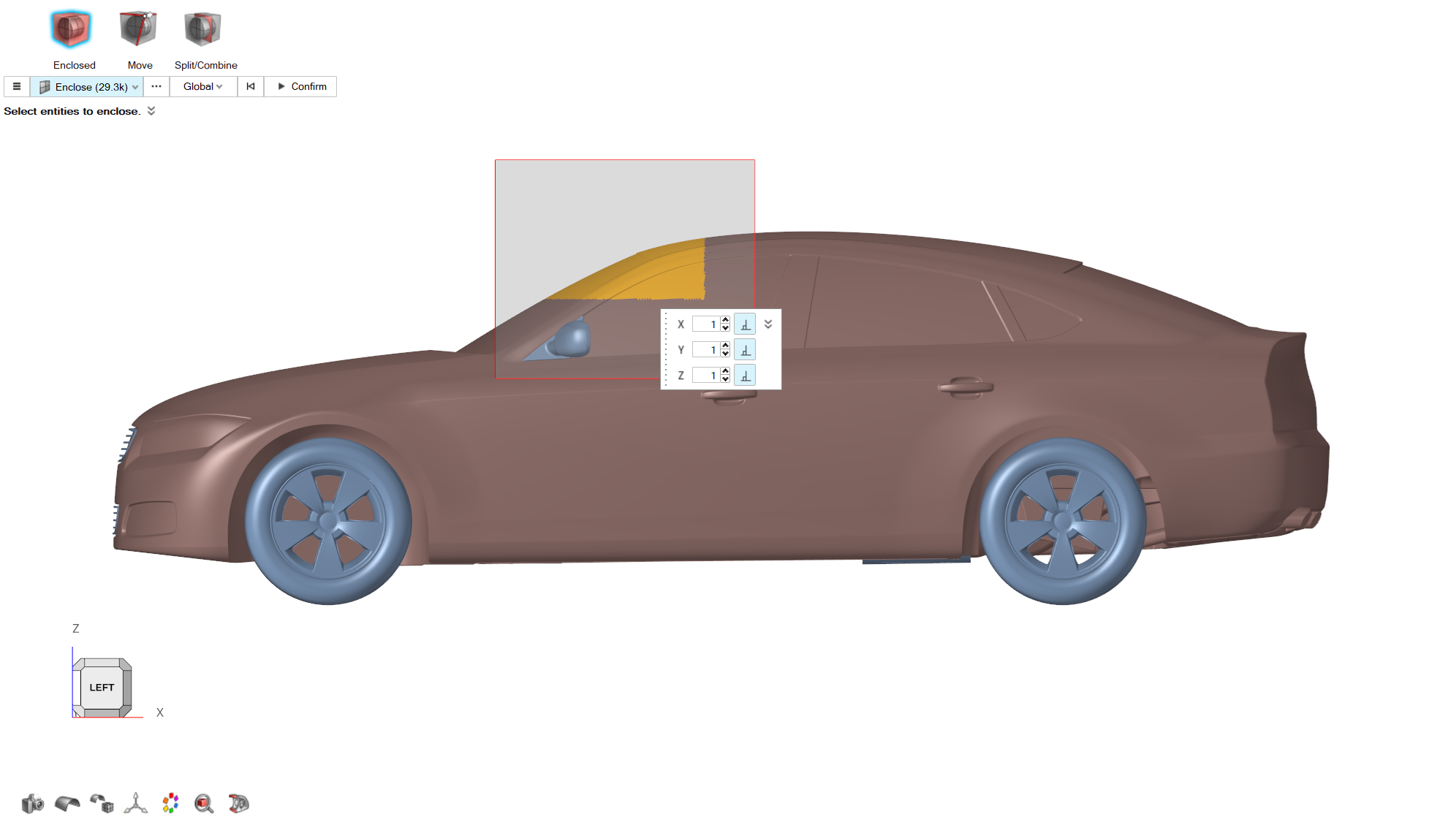
From the graphics area select the elements of the model as shown in the
following picture.
Figure 42.
Click on the Confirm button to create the control
volume.
Morph
From the Morphing ribbon, Setup
group, click the Morph tool.
From the guidebar, click on Parts and select
Body part.
From the guidebar, select MorphVolumes, and in the
graphics area select the control volume created on Step 3.
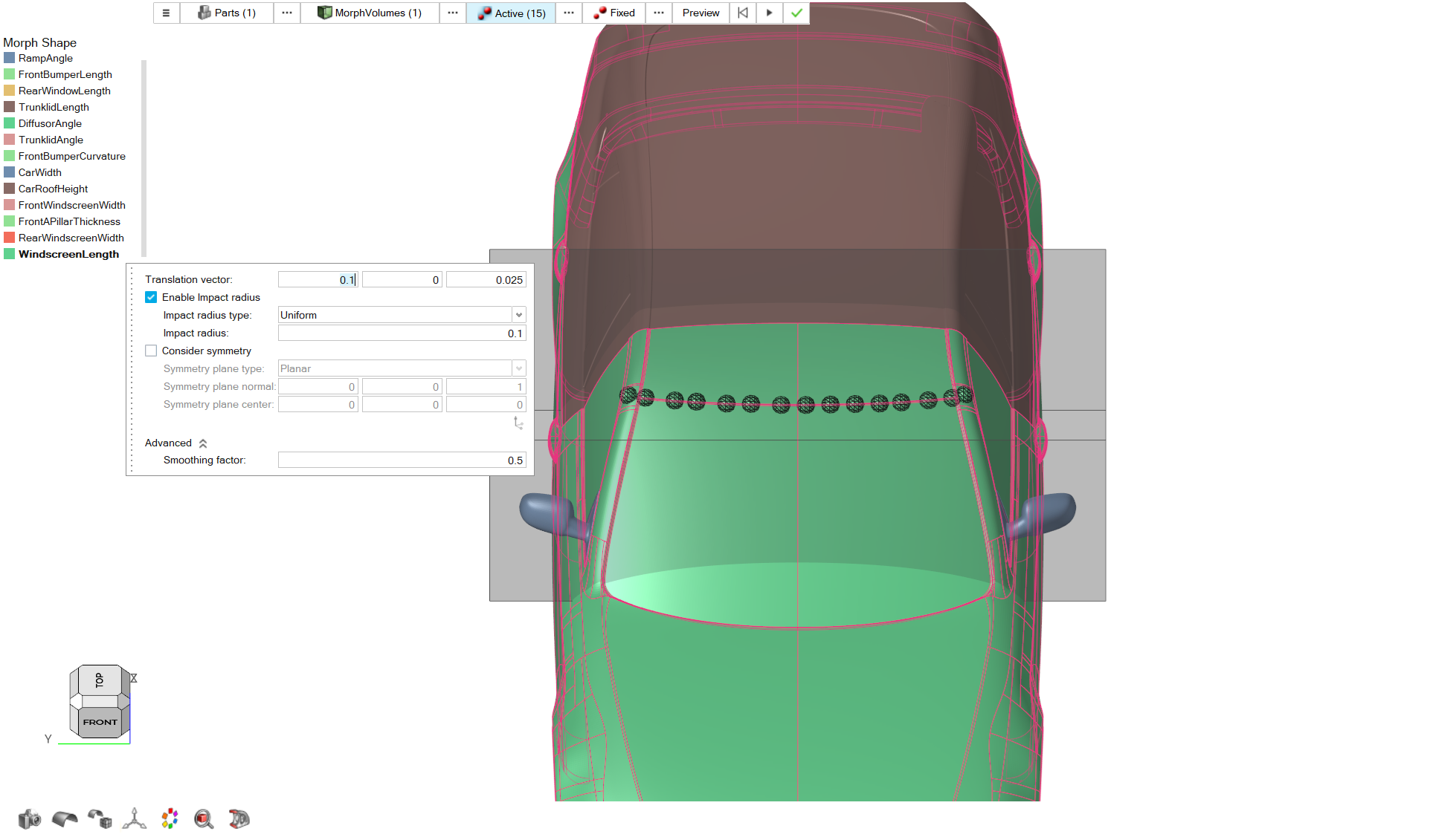
Click on Active on the guidebar.
From the graphics area create the following control points on the model.
Figure 43.
For the Translation Vector, set a value of
0.1 for X direction and 0.025
for Z direction.
Set a value of 0.1 for Impact
Radius.
From the guidebar, click on the Preview button. Examine
the resulting morphed geometry.
If the shape describes the desired geometry changes, click on the
Play button to create the shape.
From the Morph Shape menu right click on the created shape
and rename the new shape as
WindscreenLength. Click on the green checkmark to
exit the tool.
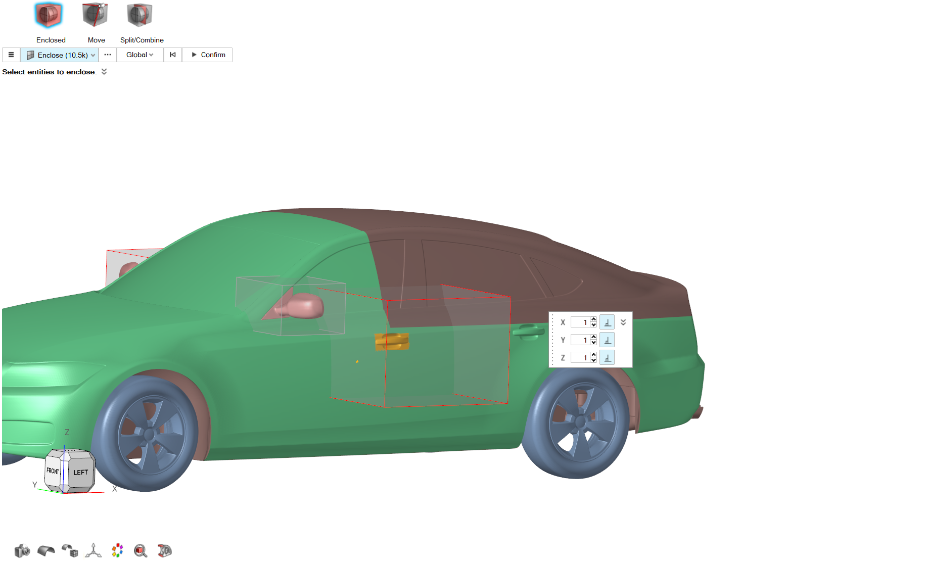
Door Handles X-Z Position
Control Volume
From the Morphing ribbon, Setup
group, click the Volumes tool, and from the secondary
tool select Enclosed tool.
From the graphics area select the elements of the model as shown in the
following picture.
Figure 44.
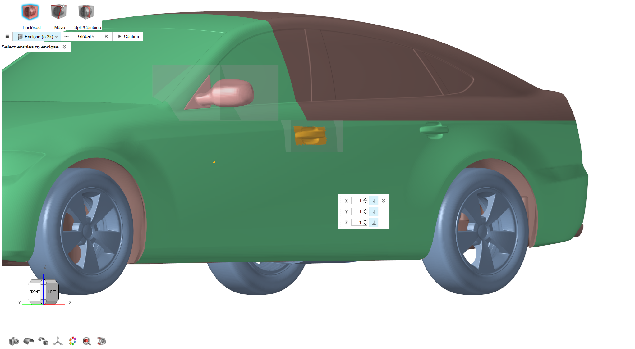
From the View cube, select the Front-Right view
angle.
While holding Shift on the keyboard, box-select the door handle elements on the
right-hand side of the model. This will remove the selected elements from the
Enclosed tool selection. The final control volume
should look like the following.
Figure 45.
Click on the Confirm button to create the control
volume.
Figure 46.
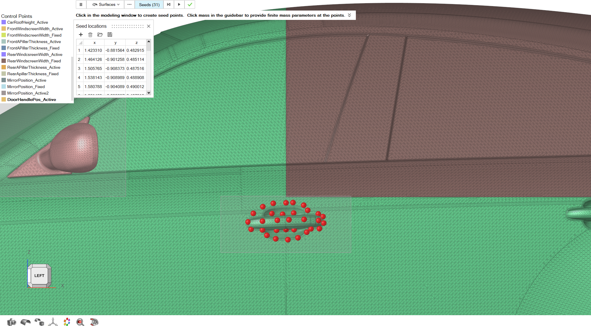
Control Points
From the Morphing ribbon, Setup
group, click the Control Points tool.
Select the Seeds option.
Place control points in the front area of the model as shown in the following
picture.
Figure 47.
Click on the Play button to create the control points
set. From the Control Points menu, right click on the newly
created control points and rename the set to
DoorhandlePos_Active.
Morph
From the Morphing ribbon, Setup
group, click the Morph tool.
From the guidebar, click on Parts and select
RearEnd_Fastback and Body
parts.
From the guidebar, select MorphVolumes, and in the
graphics area select the control volume created on Step 5.
Click on Active on the guidebar.
Click on the three dots button next to Active on the
guidebar. The Advanced Selection dialog opens. From the
list select DoorhandlePos_Active and close the
dialog.
For the Translation Vector, set a value of
0.05 for X direction and 0.01
for Z direction.
Set a value of 0.1 for Impact
Radius.
Click on the Consider Symmetry button and set a
Symmetry plane normal of (0, -1,
0).
From the guidebar, click on the Preview button. Examine
the resulting morphed geometry.
If the shape describes the desired geometry changes, click on the
Play button to create the shape.
From the Morph Shape menu right click on the created shape
and rename the new shape as
DoorHandlePosition. Click on the green checkmark to
exit the tool.
Car Length
Control Volume
Repeat Steps 1-3 to
create a control volume around the whole model.
Note: If the control volume created on Step 3 is present, you
can use that volume in the Morph tool.
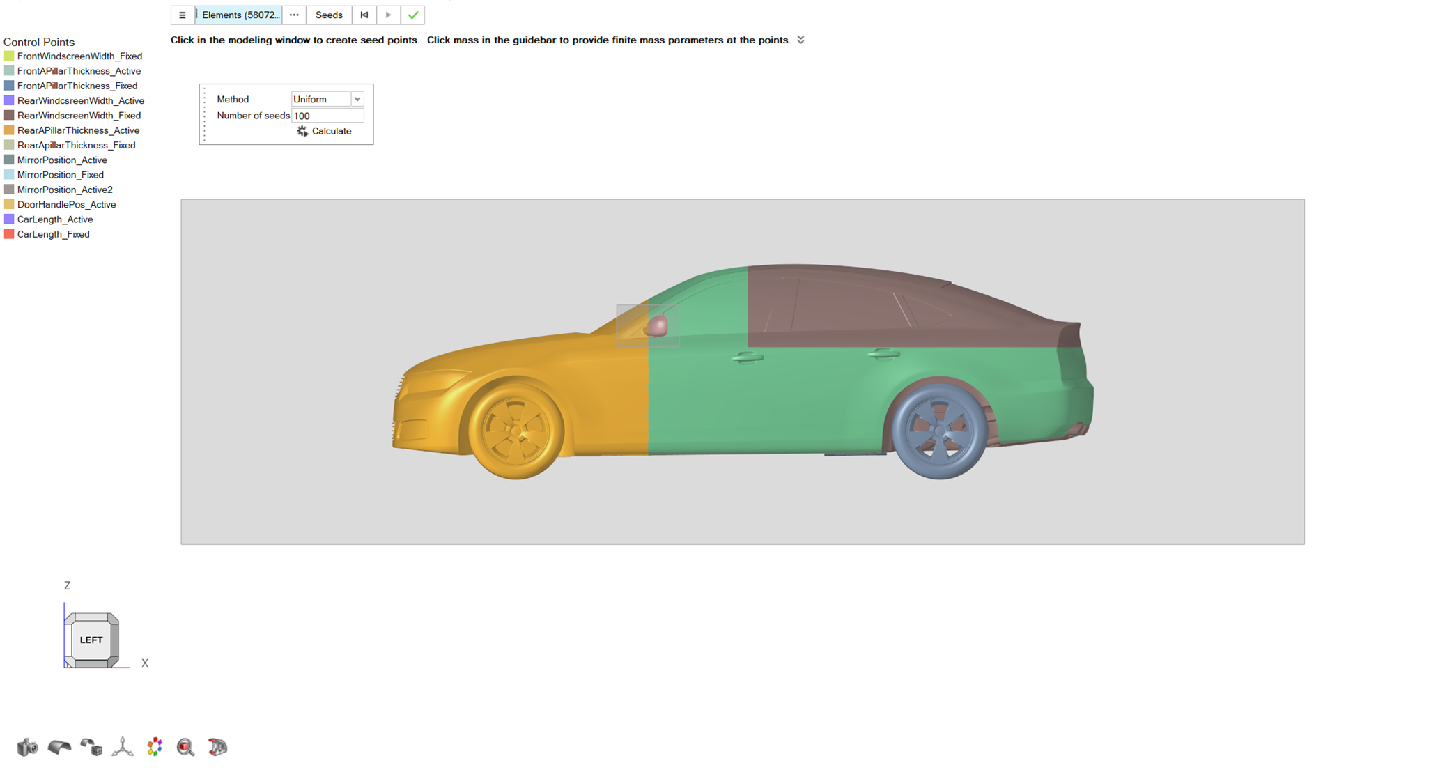
Control Points
From the Morphing ribbon, Setup
group, click the Control Points tool.
From the guidebar, set the Selection to
Elements. A dialog pops up. Select Uniform
Method and set Number of Seeds to
100.
From the graphics area select the elements on the left side of the model as
shown in the following picture.
Click on the Calculate button. Review the seeds location
and then click on the Play button to create the control
points set.
From the Control Points menu, right click on the newly
created control points and rename the set to
CarLength_Active.
Figure 48.
Repeat Steps 1-5 and create a control point set by selecting the
elements on the rear end of the model as shown in the following picture.
Rename the new set as
CarLength_Fixed.
Figure 49.
Morph
From the Morphing ribbon, Setup
group, click the Morph tool.
From the guidebar, click on Parts and select all the
parts.
From the guidebar, select MorphVolumes, and in the
graphics area select the control volume created on Step 1.
Click on Active on the guidebar.
Click on the three dots button next to Active on the guidebar. The
Advanced Selection dialog opens. From the list select
CarLength_Active and close the dialog.
Click on Fixed on the guidebar.
Click on the three dots button next to Fixed on the guidebar. The
Advanced Selection dialog opens. From the list select
CarLength_Fixed and close the dialog.
For the Translation Vector, set a value of
-0.2 for X direction.
Set a value of 1 for Impact
Radius.
From the guidebar, click on the Preview button. Examine
the resulting morphed geometry.
If the shape describes the desired geometry changes, click on the
Play button to create the shape.
From the Morph Shape menu right click on the created shape
and rename the new shape as
CarLength. Click on the green checkmark to exit the
tool.
Windscreen Inclination
Control Volume
From the Morphing ribbon, Setup
group, click the Volumes tool, and from the secondary
tool select Enclosed tool.
From the graphics area select the elements of the model as shown in the
following picture.
Figure 50.
For Buffer% set a value of
10.
Click on the Confirm button to create the control
volume.
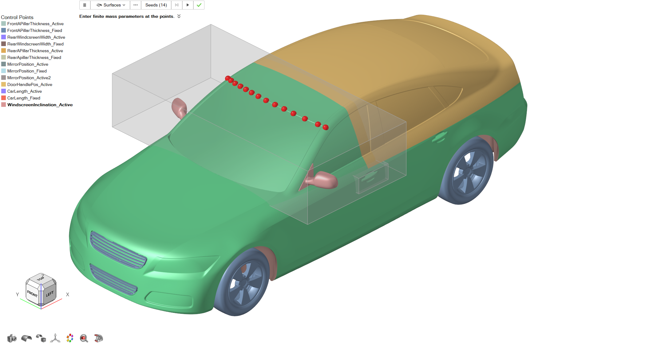
Control Points
From the Morphing ribbon, Setup
group, click the Control Points tool. Select the
Seeds option.
Place control points in the front area of the model as shown in the following
picture.
Figure 51.
Click on the Play button to create the control points
set. From the Control Points menu, right click on the newly
created control points and rename the set to
WindscreenInclination_Active.
Morph
From the Morphing ribbon, Setup
group, click the Morph tool.
From the guidebar, click on Parts and select Body,
RearEnd_Fastback parts.
From the guidebar, select MorphVolumes, and in the
graphics area select the control volume created on Step 3.
Click on Active on the guidebar.
Click on the three dots button next to Active on the
guidebar. The Advanced Selection dialog opens. From the
list select WindscreenInclination_Active and close the
dialog.
For the Translation Vector, set a value of
-0.01 for X direction and 0.04
for Z direction.
Set a value of 0.3 for Impact
Radius.
From the guidebar, click on the Preview button. Examine
the resulting morphed geometry.
If the shape describes the desired geometry changes, click on the
Play button to create the shape.
From the Morph Shape menu, right click on the created
shape and rename the new shape as
WindscreenInclination. Click on the green checkmark
to exit the tool.
Rear Window Inclination
Control Volume
From the Morphing ribbon, Setup
group, click the Volumes tool, and from the secondary
tool select Enclosed tool.
From the graphics area select the elements of the model as shown in the
following picture.
For Buffer% set a value of
10.
Click on the Confirm button to create the control
volume.
Figure 52.
Control Points
From the Morphing ribbon, Setup
group, click the Control Points tool. Select the
Seeds option.
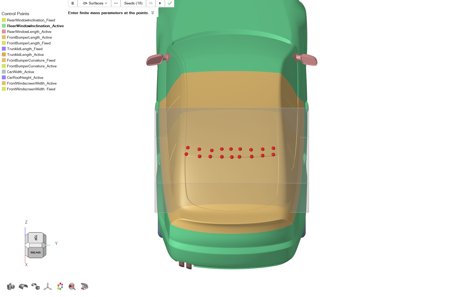
Place control points in the front area of the model as shown in the following
picture.
Figure 53.
Click on the Play button to create the control points
set. From the Control Points menu, right click on the newly
created control points and rename the set to
RearWindowInclination_Active.
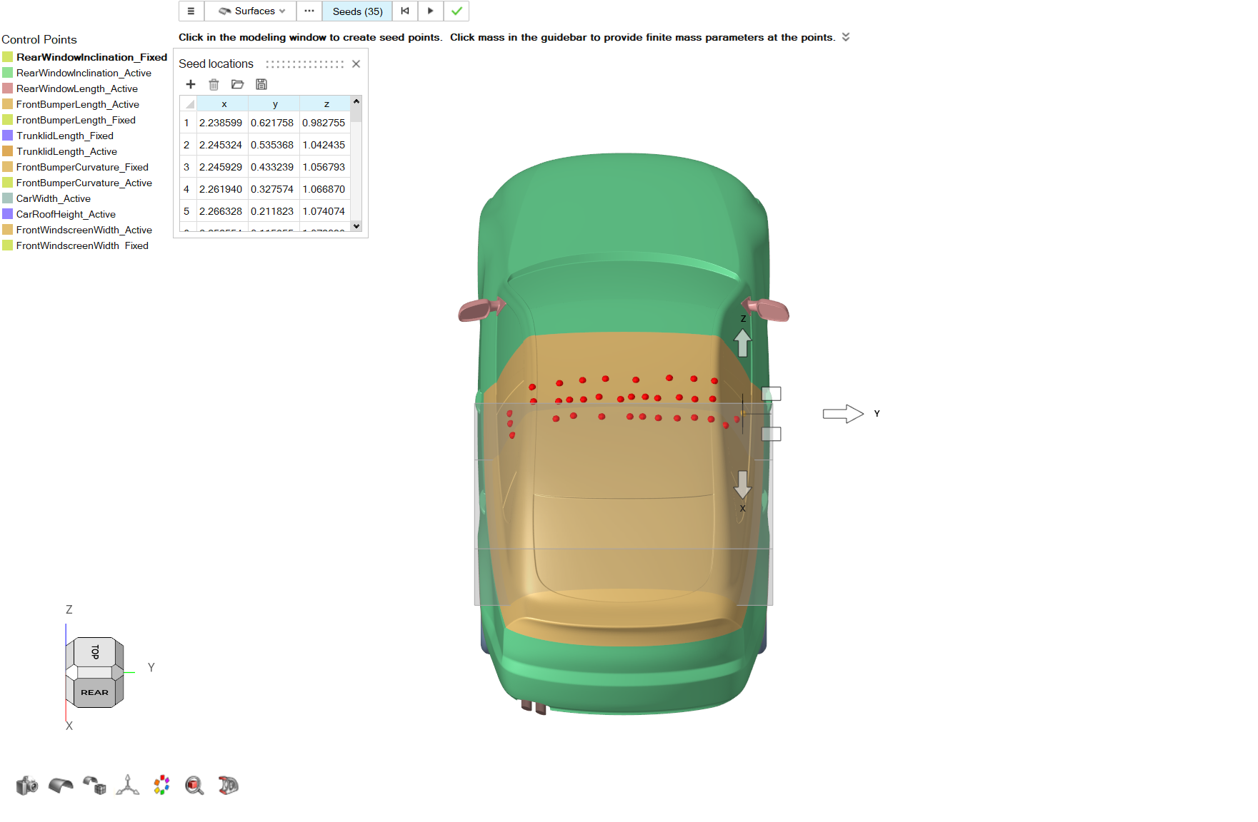
Repeat Steps 1-3 to create the control points shown in the
following picture. From the Control Points menu, right
click on the newly created control points and rename the
set to RearWindowInclination_Fixed.
Figure 54.
Morph
From the Morphing ribbon, Setup
group, click the Morph tool.
From the guidebar, click on Parts and select
Body, RearEnd_Fastback
parts.
From the guidebar, select MorphVolumes, and in the
graphics area select the control volume created on Step 4.
Click on Active on the guidebar.
Click on the three dots button next to Active on the
guidebar. The Advanced Selection dialog opens. From the
list select RearWindowInclination_Active and close the
dialog.
Click on Fixed on the guidebar.
Click on the three dots button next to Fixed on the guidebar. The
Advanced Selection dialog opens. From the list select
RearWindowInclination_Fixed and close the
dialog.
For the Translation Vector, set a value of
0.01 for X direction and 0.04
for Z direction.
Set a value of 0.5 for Impact Radius.
From the guidebar, click on the Preview button. Examine
the resulting morphed geometry.
If the shape describes the desired geometry changes, click on the
Play button to create the shape.
From the Morph Shape menu right click on the created shape
and rename the new shape as
RearWindowInclination. Click on the green checkmark
to exit the tool.
Shapes
From the Morphing ribbon, Review
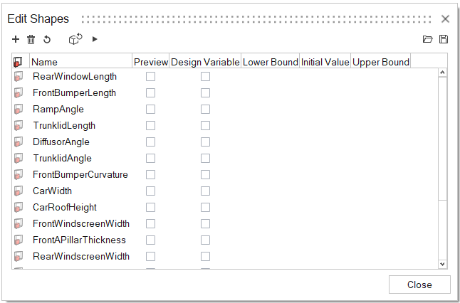
group, click on the Shapes tool.
The Edit Shapes dialog opens.
Select FrontBumperLength shape from the list.
Click on the Apply Shape button
(or right click and click on Apply by Factor option).
This will open the Apply Shape dialog where a Scale Factor
can be determined. Try applying the shape for factors of 0.5, 0.75,
1.
To remove any applied shapes from the model, use the Undo
All button in the Review group,
Shapes tool.
Figure 55. Figure 56.
Click on the Shapes tool, and from the list select
FrontBumperLength shape.
Click on the Animate button
(or right click and click on Animate option).
Figure 57.
The Animation guidebar opens.
Click on the hamburger menu and enable the Contour Plot
option.
Figure 58.
Review the animation of the selected shape.
From the guidebar, pause the animation and then click on the
Display button . This
will switch between the displayed current frame number and the displayed current
applied factor.
Use the multimedia arrow-keys on the guidebar to navigate between different
applied factors for the displayed shape.
Note: In Step 2, you can select any number of
shapes to review with the Animation tool. Note that
the tool might take longer to generate the animations if too many shapes are
selected at once and if all those shapes include a large number of
nodes.
Click on the green checkmark button to exit the tool.


 The Advanced Selection dialog opens.
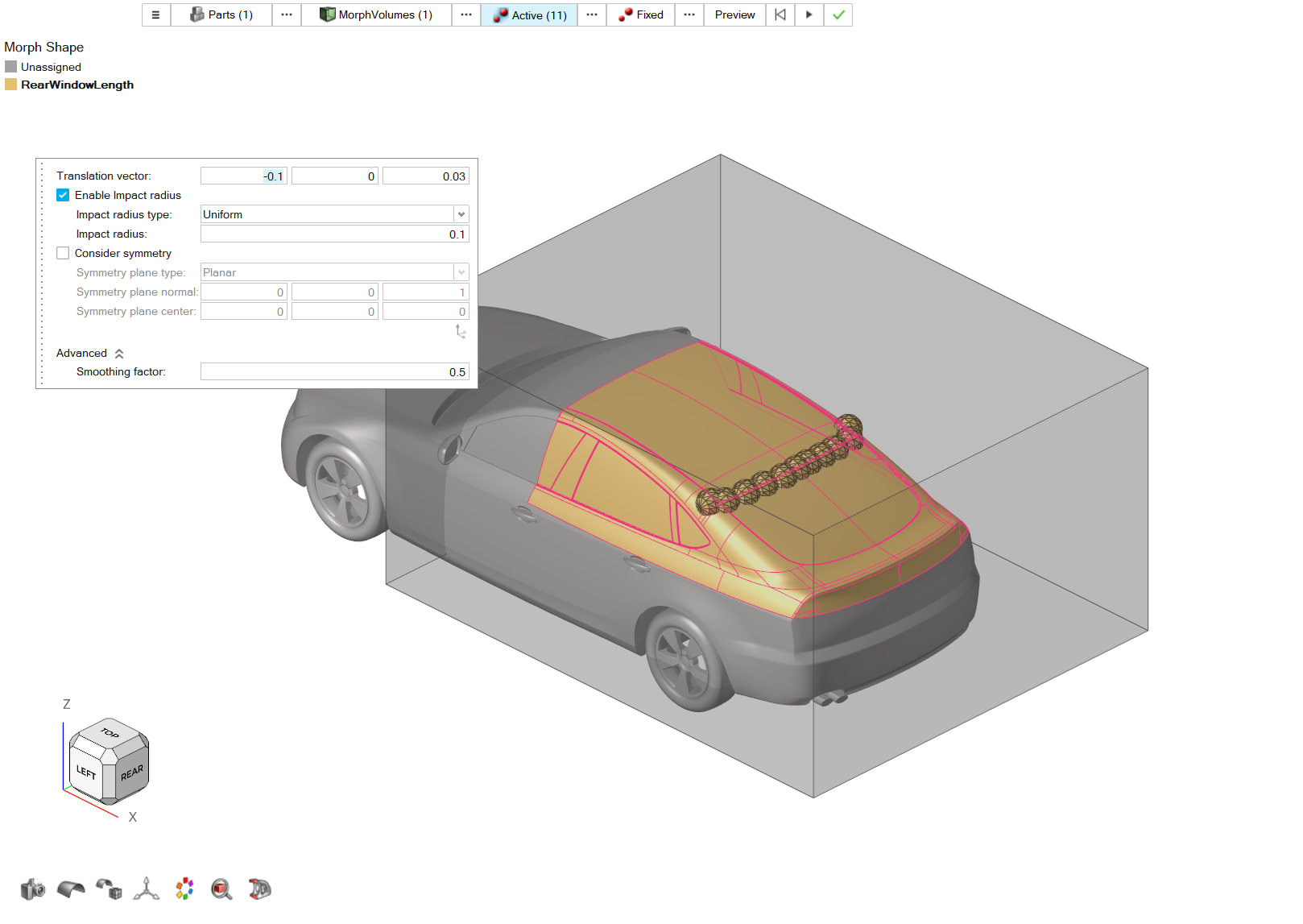
angle_ctrl_vol.png)

 (or right click and click on Apply by Factor option).
This will open the Apply Shape dialog where a Scale Factor
can be determined. Try applying the shape for factors of 0.5, 0.75,
1.
(or right click and click on Apply by Factor option).
This will open the Apply Shape dialog where a Scale Factor
can be determined. Try applying the shape for factors of 0.5, 0.75,
1.
 (or right click and click on Animate option).
 The Animation guidebar opens.
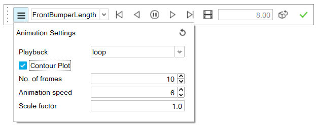
 . This
will switch between the displayed current frame number and the displayed current
applied factor.
. This
will switch between the displayed current frame number and the displayed current
applied factor.