Align and Project Elements
Use the Align/Project tool to project entities to lines, surfaces, or planes then remap and offset projected nodes.
From the Topology ribbon, click the
Align/Project tool.
Figure 1.

Align Elements
-
From the Topology ribbon, click the
Align/Project tool.
Figure 2.
- From the guide bar, select Align.
- Select nodes, node list, edges, or points as source geometry to align to target entities.
-
Select what to align entities to and complete the associated process.
Option Actions Node List - Select Node List to align entities onto a node list.
- In the modeling window, select one or more nodes.
- Click
 .
.
Edges - Select Edges to align entities onto an edge.
- In the modeling window, select one or more edges.
- Click .
Locations - Select Locations to align entities onto a location or location list.
- In the modeling window, select one or more locations.
- Click .
Lines - Select Lines to align entities onto a line.
- In the modeling window, select one or more lines.
- Click .
- Project source nodes on to a target line
Figure 3. 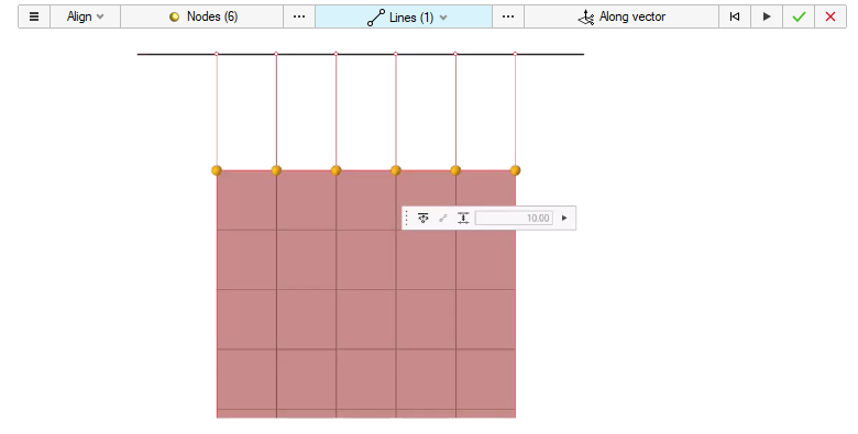
- Project nodes on to a smooth line (smooth lines can be defined using the
location entity)
Figure 4. 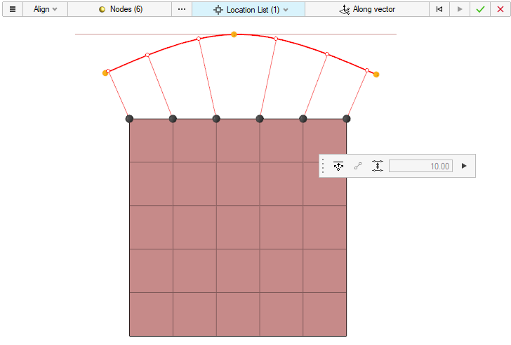
- Align nodes between start and end nodes
Figure 5. 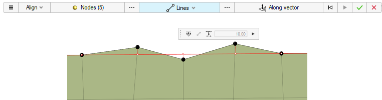
- Align nodes with respect to reference nodes
Figure 6. 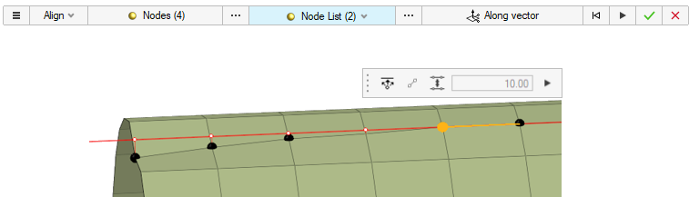
- Align + Remap
Figure 7. 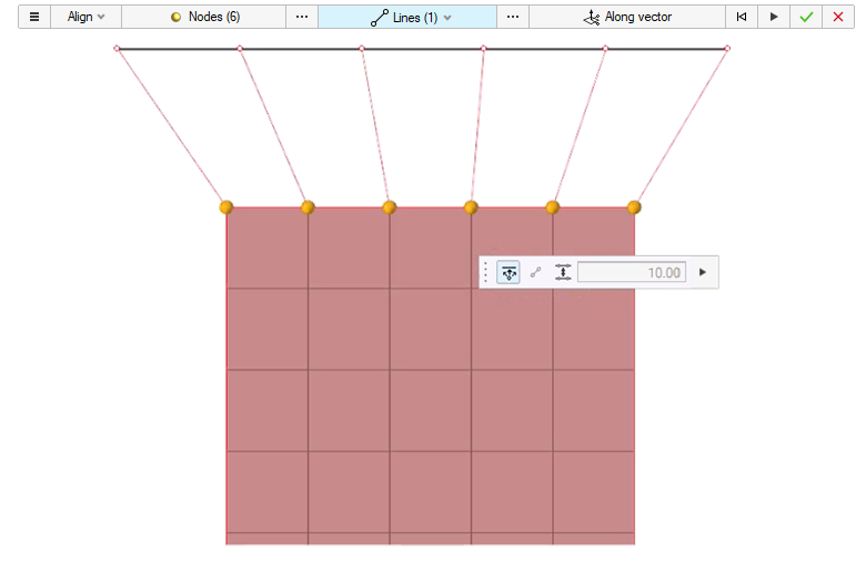
- Align + Offset
Figure 8. 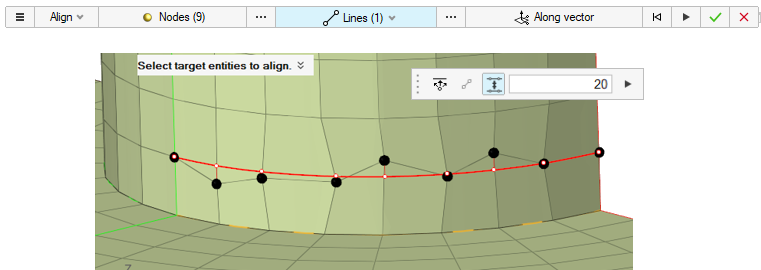
Project Elements
-
From the Topology ribbon, click the
Align/Project tool.
Figure 9.
- From the guide bar, select Project.
- Select elements, lines, nodes, or points as source geometry to project onto target entities.
-
Select what to project entities onto and complete the associated process.
- To Surfaces
- Select To Surfaces to project entities onto a surface along either a user-defined direction or the normal to the surface.
- In the modeling window, select one or more surfaces.
- Click .
Figure 10. 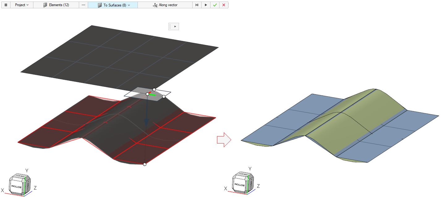
- To Plane
- Select To Plane to project entities onto a plane along a user-defined direction.
- In the modeling window, select a plane and
use the Plane tool to project.
The plane could be aligned to a surface/mesh/nodes, and so on.
- Click .
Figure 11. 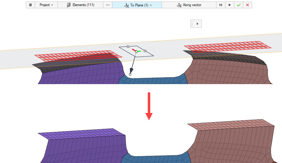
Figure 12. 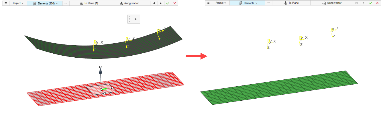
- To Vector
- Select To Vector to project entities onto a vector along a user-defined direction.
- In the modeling window, place the vector and
use the Vector tool to define the direction of projection.
All of the selected entities are projected along the same direction.
- Click .
- To Surfaces