Features
Detect, review, and manage geometric holes, fillets, flanges, and logos.
Create Features
Use the Features tool to find and create geometric features in the displayed model.
-
From the Topology ribbon, click the
Features tool from the Features tool group.
Figure 1. 
The Feature Detection Parameters dialog opens. - Select the feature types you want to find and enter the minimum and maximum dimensions to include in the detection.
- Optional: Select Delete existing features to delete existing features before detection.
- Optional: Select Preserve edited features to preserve manually created/edited features before detection.
-
Click Find to begin the detection process.
Tip: Using larger tolerances will capture more features but will increase processing time.The Features Browser opens automatically.
- Optional:
From the Topology ribbon, click the Create
Features tool from the Features tool group to manually create
features.
Figure 2. 
Tip:- Select the Auto Compute check box to automatically compute the parameters.
- In the Features Browser, click
 to manually create
features.
to manually create
features.
- Optional:
From the Topology ribbon, click the List
Features tool from the Features tool group to open the Features Browser.
Figure 3. 
-
Use the Features Browser to select, review, and edit the
detected features.
By now, the feature entities are already in the model and can be also accessed via the Model Browser or by selecting them directly in the modeling window.
- Status
- Green – Auto detected
- Empty
- A feature that does not have any entities.
- Edit Feature
- Edit a feature using the Entity Editor in the Features Browser
- Validate
- Select Validate from the right-click context menu to synchronize data and attributes
for the chosen features with their current geometry or mesh.Tip: Validating the selected features also updates the Invalid column in the Features Browser. Features can be flagged as invalid if their associated geometries have been deleted or modified in ways that cannot be referenced anymore. Invalid features can still be selected and used, but they may have some missing associated geometries or inaccurate dimensions.
 Delete features
- Deletes the selected features from the model. To remove individual features, select them anywhere and press Delete.
- Fit
- Select Fit from the right-click context menu to adjust the view of the selected features.
- You can interact with features in the modeling window by setting the entity selector filter to Features with the mouse or by pressing the E key.
- Selection conversion between features and surfaces, lines, or elements (depending on feature type) is supported by switching the filter type with an active selection.
- Advanced selection methods are available for selecting features By Config, and geometry or mesh By Features.
Feature Types
HyperMesh supports the detection and management of the following feature types:
- Geometry
- 2D holes
- 3D holes
- Flanges
- Fillets
- Logos
- Mesh (FE)
- 2D holes
- 3D holes
- Flanges
- Both (Geometry + Mesh Associativity)
- 2D holes
- 3D holes
- Flanges
2D and 3D Holes
The following shapes and measured dimensions are supported for 2D holes:
- Circular
-
Figure 5. 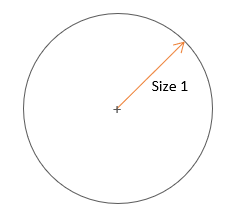
- Rounded
-
Figure 6. 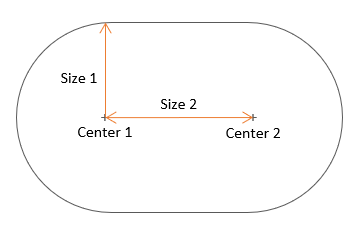
- Square
-
Figure 7. 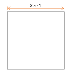
- Rectangular
-
Figure 8. 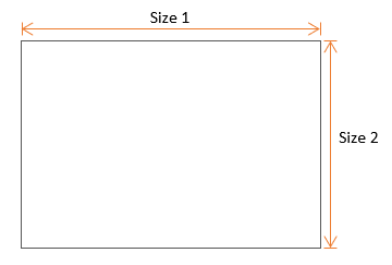
- General
-
Figure 9. 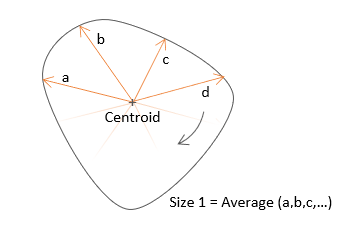
- Defeature - Selected holes are defeatured using the same commands used by .
- Fill - Selected holes are filled with a filler surface using the same commands used by .
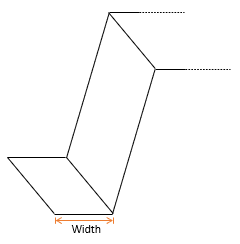
Flanges
Fillets
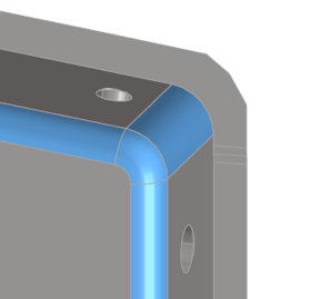
Fillets can be curved rounds (exterior) or fillets (interior) connecting surface edges in place of a corner. Their measured dimensions are minimum and maximum radius, minimum and maximum width, and minimum and maximum angle.
- Defeature - Selected fillets are defeatured using the same commands used by .
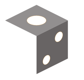
Logos
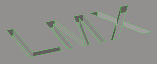
Logos are collections of surfaces representing symbols or letters that are embossed, etched, or machined into other surfaces. Their measured dimensions are size and height.
- Defeature - Selected logos are defeatured using the same commands used by .