
Joints
Use the Joints tool to create and edit joints.
Joints create lower pair constraints. A constraint is defined as the removal of a degree of freedom (DOF) from a body. Each body has a total of six DOF, three translational and three rotational.
A lower pair constraint is an idealized form of constraint in which the constraint can be represented by two reference frames (coordinate systems), belonging to two different bodies.
| Joint Type | Description | Removes Translational DOF | Removes Rotational DOF | Removes Total Number of DOF | Add Friction |
|---|---|---|---|---|---|
| Revolute
|
A one DOF constraint, also known as a pin or hinge joint, enabling rotation around a single axis. It is commonly used in mechanisms such as door hinges and folding structures. | 3 | 2 | 5 | Yes |
| Ball and Socket
|
A three DOF constraint, also known as a spherical joint, allowing rotation around three axes. It is commonly used in mechanisms such as steering racks connected to knuckles via tie rods and knuckle-to-control arm joints. | 3 | 0 | 3 | Yes |
| Translational
|
A one DOF constraint, enabling linear motion along a single axis. It is commonly used in mechanisms such as splined shafts and slider assemblies. | 2 | 3 | 5 | Yes |
| Universal
|
A two DOF constraint, enabling rotation about two axes. While functionally identical to a Hooke joint, the distinction between the two lies in how they are defined. Universal joints are commonly used in applications such as propeller shafts, drive shafts, and steering columns. | 3 | 1 | 4 | Yes |
| Inline
|
A four DOF primitive constraint that restricts motion such that the origin of a reference marker on one part (Part 1) translates along the Z-axis of a reference marker on another part (Part 2). It allows three rotational and one translational DOF between the two parts. * | 2 | 0 | 2 | No |
| Fixed
|
A zero DOF constraint that creates a rigid connection between two parts, forcing them to move as a single unit. It is used to simulate connections where relative displacement is idealized as zero, such as bolted or welded joints and components that remain fixed in both motion and orientation. | 3 | 3 | 6 | No |
| Inplane
|
A five DOF primitive constraint that restricts one part (Part 1) to remain within the XY plane defined by the connected part (Part 2). It allows three rotational and two translational DOF while preventing motion perpendicular to the plane. * | 1 | 0 | 1 | No |
| Cylindrical
|
A two DOF constraint, similar to a translational joint, but it adds an additional rotational DOF. It is commonly found in mechanisms such as shock absorber tubes, rods, and hydraulic cylinder-rod pairs. | 2 | 2 | 4 | Yes |
| Planar
|
A three DOF constraint that restricts a plane on one part to remain within a plane defined on another part. The two planes can only move and rotate parallel to each other. | 1 | 2 | 3 | No |
| Constant Velocity
|
A two DOF constraint that restricts the rotation of a part about a specified axis to be equal to the rotation of the other part. Constant velocity joints are widely used in drive shafts of vehicles with independent suspension. | 3 | 1 | 4 | No |
| AtPoint
|
A three DOF constraint that is identical to the ball and socket joint. | 3 | 0 | 3 | No |
| Orientation
|
A three DOF constraint that restricts all rotational motions between two parts, while allowing translational motions to remain free. * | 0 | 3 | 3 | No |
| ParallelAxes
|
A four DOF primitive constraint, restricting two parts to rotate only about a common axis. All translational motion is free. * | 0 | 2 | 2 | No |
| PerpendicularAxes
|
A five DOF primitive constraint, restricting an axis on one part to remain perpendicular to an axis on another part. All translational motion is free. * | 0 | 1 | 1 | No |
| Screw
|
A five DOF constraint, imposing a relationship between the rotation of one part (Part 1) about an axis to the translation of the other part (Part 2) along another axis. The relationship is defined by the pitch of the joint, where one full rotation of Part 1 translates Part 2 by a distance equal to the pitch. Screw joints are commonly used in applications such as bolt and nut assemblies and rack-and-pinion steering mechanisms. | 1 | 0 | 1 | No |
- Non-compliant Joints
- Non-compliant joints act as pure constraints and allow relative motion only between the DOF of that particular joint type.
- Compliant Joints
- Compliant joints are identical to bushings and allow relative motion in all six DOF. The relative motion is dependent on the stiffness and damping of the compliant joint. In order for a joint to be compliant, the Compliant option must be enabled.
Add a Joint
-
On the Motion ribbon, under Profile, select Analyst.

-
Under Connections, select the Joints tool.
Tip: To find and open a tool, press Ctrl+F. For more information, see Find and Search for Tools.The guide panel is displayed.Figure 1. 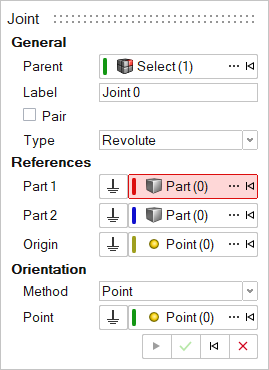
- Optional: To select a Parent system, click ....
- Optional: Edit the Label.
- Optional:
To create a pair of entities, turn on Pair.
Note: An entity pair is a combination of two entities of the same type within a single definition. It has two sides, Left and Right. Entities with properties can be marked as symmetric with one side as the Leading side. The other side then becomes the Following side. The properties of the Following side are reflected from the Leading side across the Global X-Z plane.
- To create a model that is symmetric about the X-Z plane, in the Property Editor, under General, set Symmetry to Left or Right.
- To create a model that is asymmetric, set Symmetry to None.
-
Select a joint type.
Note: For more information, see Joints.
-
Resolve the Part 1 collector by clicking on a part
in the modeling window or by using the Advanced selector
....
The selected body should now be highlighted in red.
-
Resolve the Part 2 collector by picking a different
part.
The selected body will be highlighted in blue.
-
Select a hard point as the origin.
- To select an existing hard point, do one of the following:
- In the modeling window, select the hard point.
- Click ..., and then select a point in the Model Tree.
- To create a new hard point, select a vertex, midpoint, edge or face on a part. When an edge or face is selected, the point is created at the center of the edge or face.
- To select the global origin, click
 .
.
- To select an existing hard point, do one of the following:
-
Select a method of orientation.
Note: Depending on the type of joint, select either one or two axes. Each axis can be defined either by an endpoint using a Hard Point or by a Vector.
-
Click Apply
 .
The entity appears in the Model Browser and its properties appear in the Property Editor.
.
The entity appears in the Model Browser and its properties appear in the Property Editor. -
Right-click and mouse through the check mark to exit, or double-right-click.
Note: By default, variables names of entities in Inspire follow a certain convention. For example, all joint entities have a variable name starting with “Joint_”. This is the recommended convention to follow when building models in Inspire since it has many advantages in model editing and model manipulation.
Edit a Joint
Edit a joint using the Joints tool or Property Editor.
-
On the Motion ribbon, under Profile, select Analyst.
-
Choose from the following methods:
Table 2. Edit methods To use this method Do this Advanced Joints tool - On the Motion ribbon, under Profile, select
Analyst.
- Under Connections, select the
Joints tool.
- The guide panel appears.
- To edit the References, follow steps in the Add a Joint section.
Property Editor - From the View menu, select Property Editor.
- On the Motion ribbon, under Profile, select
Analyst.
- Right-click and mouse through the check mark to exit, or double-right-click.
Joint Properties
Descriptions of joint properties in the Property Editor.
| Property | Description |
|---|---|
| General | |
| Label | Descriptive label for the entity |
| Variable Name | Variable name of the entity |
| ID | Integer identifier |
| Part 1 | First part of the joint |
| Part 2 | Second part of the joint |
| Symmetry |
|
| Origin | Origin of the joint |
| Type | Type of joint |
| Use Virtual | Set the joint as virtual |
| Compliant | Compliance state of joint. True or False. Joint is compliant if True and represents a bushing. This property is visible when the joint is created with Allow Compliance option. |
| Friction | |
| Use Friction | Turn on friction for the joint. Refer to Friction Properties section. |
| Orientation | Use this section to orient the non-compliant joint. Types and methods of orientation depend on Joint Type. |
| Alignment Type (Type 1 | Type 2) | Applicable for Universal, Inline, Inplane, Planar, and ParallelAxes only. Select the type of alignment desired. Refer to the comment below. |
| Method (Method 1 | Method 2 ) | Method of orienting the axis or axes of the joint. Available choices are Point and Vector. |
| Point|Vector | Select a Point or a Vector based on the Method selected. The joint will be oriented along the direction of the point or the vector from the Origin. |
| Initial Conditions | Apply initial velocity conditions to the joint. Applicable for Revolute, Translational and Cylindrical joints. |
| Use rotational | Apply initial rotational velocity for revolute or cylindrical joint |
| Rotational Velocity | Rotational velocity value in rad/sec |
| Use translational | Apply initial rotational velocity for translational or cylindrical joint |
| Translation Velocity | Translational velocity value in model velocity units |
| FlexBody Connection Radius | |
| Override | Override automatic connection radius. Applicable when the joint is applied on a flexbody. |
| Connection radius | Overriding search distance to connect the entity with rigid elements when the joint is applied on a flexbody Refer to Connection Radius for more details. |
- Note on Non-compliant Joint Orientation
- By defining a joint between two parts , the constraint between the parts
is imposed using two markers or coordinate systems (I Marker and J
Marker) belonging to each part. By orientating a joint, these markers
are oriented in certain directions along or about which the joint has
degrees of freedom (usually Z axis of the markers).
Figure 2. Z Axes of the revolute joint oriented along a point 
- Alignment types
- Certain joints have different ways of alignment based on the joint
type.
- Universal joints can be aligned either by aligning the Shaft direction or the direction of the Crosspin (which is perpendicular to the shaft and part of the yoke) on either side.
- Inline joints can be aligned by either aligning the axis along a point or a vector or providing another origin Origin 2.
- Inplane, Planar, and Parallel axis joints can be aligned by either specifying the normal to the plane (a point or a vector) or defining the plane with two inputs using points or vector.
For information on virtual joints, see Constraint: Joint, Comment 17 in the MotionSolve documentation.
- Adding Friction
- Friction can be added to the following non-compliant joints - Ball, Revolute, Translation, Cylindrical, and Universal. Refer to Edit Joints, Joint Properties table in the HyperWorks documentation for more information.