
Primitives
A primitive is a simple geometric shape defined using hard points and vectors. Examples include a box, cylinder, or sphere.
It can be defined as a pair entity, which helps in creating models that have identical entities across the x-z plane. The pair entity can have asymmetric or symmetric properties. When symmetric, the properties from one side are mirrored to the other side about the x-z plane.
Add a Primitive
Create a primitive using a hard point as the origin and, when applicable, using one or more hard points or a vector to define the orientation.
-
On the Motion ribbon, under Profile, select Analyst.

-
Under Create, select the Primitives tool.

Tip: To find and open a tool, press Ctrl+F. For more information, see Find and Search for Tools.The guide panel is displayed.Figure 1. 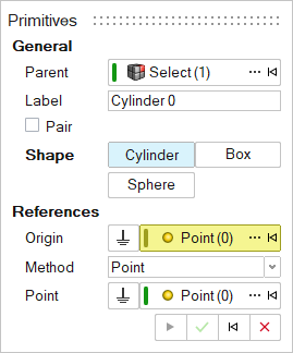
- Optional:
To select a Parent system, click the Advanced selector
....
Note: If a system or an entity in a system is selected before entering an entity context, the system is preselected as the parent.
- Optional: Edit the Label.
- Optional:
To create a pair of entities, turn on Pair.
- To create a model that is symmetric about the x-z plane, in the Property Editor, under General, set Symmetry to Left or Right.
- To create a model that is asymmetric, set Symmetry to None.
-
Choose a Shape:
- Cylinder
- Box
- Sphere
-
Resolve the References:
For a Cylinder:
- Select an Origin, which is one end of the
cylinder, using one of the following methods.
- In the modeling window, select an existing hard point.
- Select a vertex, edge, or face of a geometry. This will automatically create a new hard point. When an edge or face is selected, the point is created at the center of the edge or face.
- Click the Advanced Selector … and make your selection in the Model Tree.
- To select the global origin, click
Ground
 .
.
- Define the Alignment to orient the cylinder along its length.
Table 1. To use this Alignment method Do this Point Do one of the following: - In the modeling window, select an existing hard point.
- Select a vertex, edge, or face of a geometry. This will automatically create a new hard point. When an edge or face is selected, the point is created at the center of the edge or face.
- Click the Advanced Selector … and make your selection in the Model Tree.
- To select the global origin, click
Ground
.
Vector Do one of the following: - In the modeling window, select an existing vector.
- Select an edge or circular face of a geometry. A vector is created along the edge or center of the face. A hard point is also created for the vector origin.
- Click the Advanced Selector … and make your selection in the Model Tree.
- To select the global origin, click
Ground
.
For a Box:
- Select a Type.
- Center: The origin of the box's coordinate system origin is at the center.
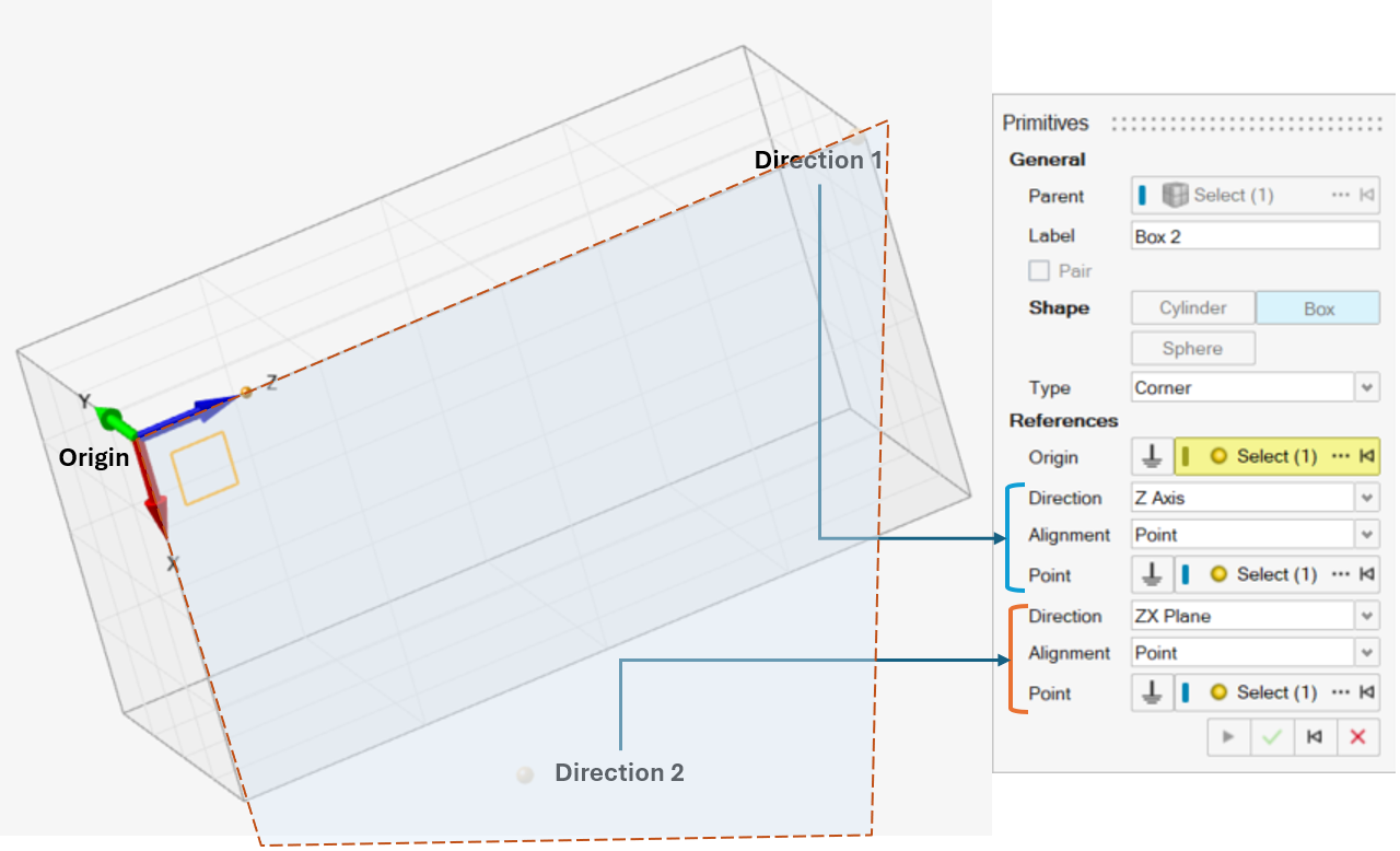
- Corner: The origin of the box's coordinate system origin is at a corner.
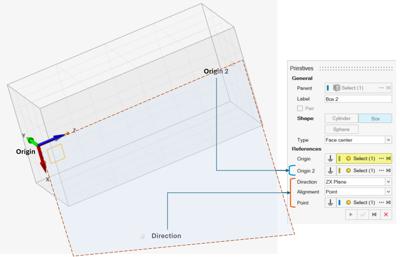
- Face Center: The box is defined using 2 points that form one set of opposite faces.
- Select an Origin using one of the following
methods.
- In the modeling window, select an existing hard point.
- Select a vertex, edge, or face of a geometry. This will automatically create a new hard point. When an edge or face is selected, the point is created at the center of the edge or face.
- Click the Advanced Selector … and make your selection in the Model Tree.
- To select the global origin, click
Ground
.
- Select the directions.
For Center and Corner:
- To orient the box, select a
Direction:
- X Axis
- Y Axis
- Z Axis
- Define the Alignment.
To use this Alignment method Do this Point Do one of the following: - In the modeling window, select an existing hard point.
- Select a vertex, edge, or face of a geometry. This will automatically create a new hard point. When an edge or face is selected, the point is created at the center of the edge or face.
- Click the Advanced Selector … and make your selection in the Model Tree.
- To select the global origin, click
Ground
.
Vector Do one of the following: - In the modeling window, select an existing vector.
- Select an edge or circular face of a geometry. A vector is created along the edge or center of the face. A hard point is also created for the vector origin.
- Click the Advanced Selector … and make your selection in the Model Tree.
- To select the global origin, click
Ground
.
- Select another Direction. Based on the first direction, select one plane among the two listed. For example, if the Z axis was selected earlier, then ZX Plane and ZY Plane can be selected.
- Define the Alignment.
To use this Alignment method Do this Point Do one of the following: - In the modeling window, select an existing hard point.
- Select a vertex, edge, or face of a geometry. This will automatically create a new hard point. When an edge or face is selected, the point is created at the center of the edge or face.
- Click the Advanced Selector … and make your selection in the Model Tree.
- To select the global origin, click
Ground
.
Vector Do one of the following: - In the modeling window, select an existing vector.
- Select an edge or circular face of a geometry. A vector is created along the edge or center of the face. A hard point is also created for the vector origin.
- Click the Advanced Selector … and make your selection in the Model Tree.
- To select the global origin, click
Ground
.
Table 2. Center and Corner Boxes 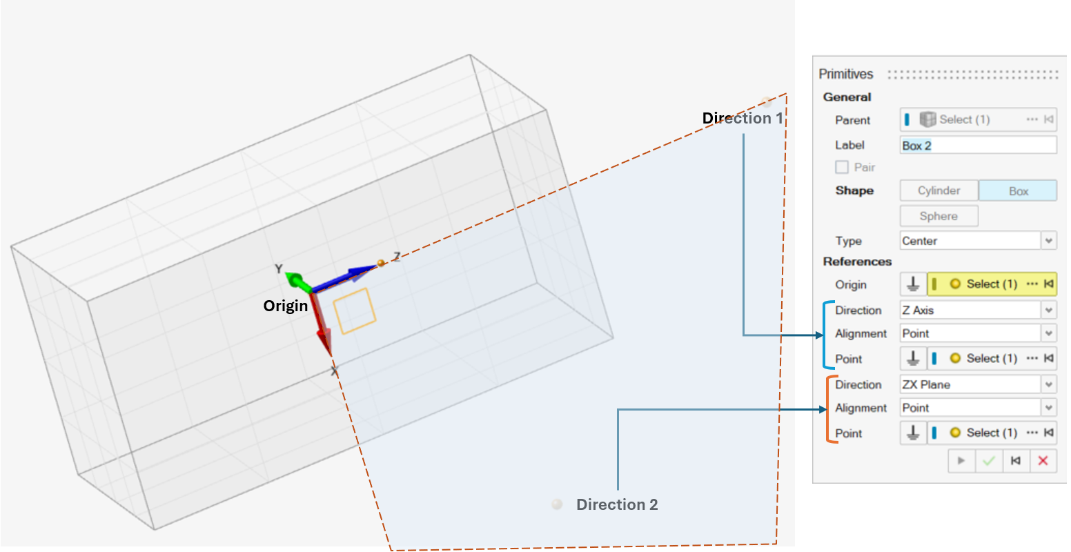
- To orient the box, select a
Direction:
For Face Center:- Select Origin 2 using one of the following
methods.
- In the modeling window, select an existing hard point.
- Select a vertex, edge, or face of a geometry. This will automatically create a new hard point. When an edge or face is selected, the point is created at the center of the edge or face.
- Click the Advanced Selector … and
make your selection in the Model Tree.
This is sets the Z axis of the coordinate system along the selected point, with length in Z direction being the distance between Origin and this point.
- Select the other direction by selecting either ZX Plane or ZY Plane
- Define the Alignment.
To use this Alignment method Do this Point Do one of the following: - In the modeling window, select an existing hard point.
- Select a vertex, edge, or face of a geometry. This will automatically create a new hard point. When an edge or face is selected, the point is created at the center of the edge or face.
- Click the Advanced Selector … and make your selection in the Model Tree.
- To select the global origin, click
Ground
.
Vector Do one of the following: - In the modeling window, select an existing vector.
- Select an edge or circular face of a geometry. A vector is created along the edge or center of the face. A hard point is also created for the vector origin.
- Click the Advanced Selector … and make your selection in the Model Tree.
- To select the global origin, click
Ground
.
 For a Sphere, select an Origin, which is the center of the sphere, using one of the following methods.
- In themodeling window, select an existing hard point.
- Select a vertex, edge, or face of a geometry. This will automatically create a new hard point. When an edge or face is selected, the point is created at the center of the edge or face.
- Click the Advanced Selector … and make your selection in the Model Tree.
- To select the global origin, click Ground
.
- Select an Origin, which is one end of the
cylinder, using one of the following methods.
-
Click Apply
 to create the entity and edit it further. For more information, see Edit a Primitive, or click OK
 to exit the tool on entity creation.
The primitive entity is created. It is now listed in the Model Browser and its properties appear in the Property Editor.
- Right-click and mouse through the check mark to exit, or double-right-click.
Edit a Primitive
Edit a primitive part using the Primitives tool or Property Editor.
- Select the primitive.
-
Choose from the following methods:
Table 3. To use this method Do this Primitives tool - On the Motion ribbon, under Profile, select
Analyst.
- Under Create, select the
Primitives tool.The guide panel is displayed. Manipulators appear around the primitive.
Figure 2.
Example: The Cylinder primitive appears as shown below in Edit mode.Figure 3. 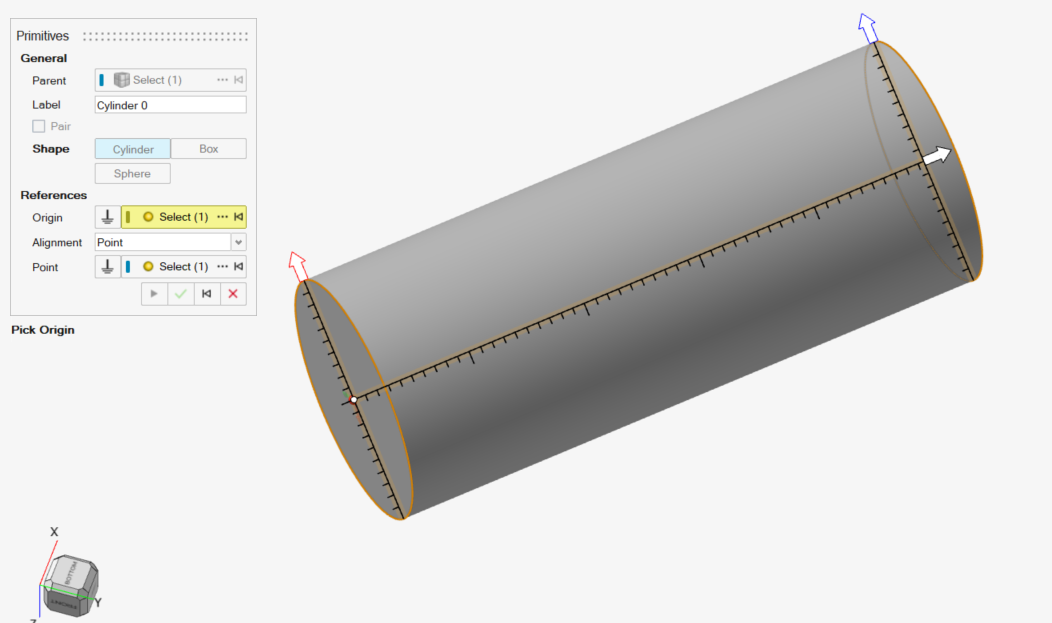
- Edit the Label or any References from the guide panel. Follow instructions in Add a Primitive for selecting References.
- Drag the manipulators to edit dimensions such as the Radius or Length.
- Right-click and mouse through the check mark to exit, or double-right-click. Or click
Cancel
 in the
guide panel.
in the
guide panel.
Property Editor The selected primitive's properties are listed in the Property Editor. Refer to Primitive Properties. - On the Motion ribbon, under Profile, select
Analyst.
Primitive Properties
Descriptions of primitive properties in the Property Editor.
| Property | Description |
|---|---|
| General | |
| Name | The entity's name |
| Variable Name | The variable name, a unique identifier string of the entity |
| ID | A unique identifying integer |
| Ground | Ground the part. |
| Rigid Group | Read-only. The rigid group name, if the primitive is part of a rigid group. |
| Material | Assign a material to the primitive. |
| Appearance | |
| Color | Assign a color to the primitive. |
| Transparency | Set the transparency level for displaying parts from 0 to 100%. |
| Geometric Properties | |
| Cylinder | |
| Origin | The center of one of the cylinder's bases. |
| Align Method | The length of the cylinder can be assigned to a
reference geometry:
|
| Point (Alignment) | Point indicating the orientation. Active only if the Align Method is Point. |
| Vector (Alignment) | Vector indicating the orientation. Active only if the Align Method is Vector. |
| Autolength | Set the cylinder length as the distance between the Origin and the Alignment Point. Applicable when the Align Method is Point. |
| Length | The cylinder's length. Applicable when the Align method is Vector and Autolength is turned off. |
| Radius 1 | The radius of the cylinder base containing the origin. |
| Radius 2 | The radius of the opposite cylinder base, which doesn't contain the origin. By default, the value is 1. |
| Box | |
| Origin | The box's origin. |
| Type | The box type:
|
| Direction (1) | First directional axis to orient:
|
| Method 1 | Method of orienting direction. Point or Vector. (Only applicable to Center and Corner boxes.) |
| Point 1 | Active only if Method 1 is Point. Point indicating the direction of the selected axis from the Origin. (Only applicable to Center and Corner boxes.) |
| Vector 1 | Active only if Align Method 1 is Vector. Vector indicating the direction of the selected axis from the origin. (Only applicable to Center and Corner boxes.) |
| Direction (2) | Plane to orient based on the Direction 1 selection. XY | XZ | YX | YZ | ZX| ZY. For a Face Center box, only ZX | ZY planes are available. |
| Method 2 | Method of orienting the plane. Point or Vector. |
| Point 2 | Active only if Align Method 2 is Point. Point indicating direction of the plane such that the selected point lies in the plane. |
| Vector 2 | Active only if the Align Method is Vector. Vector indicating the direction of the plane such that the selected vector lies in the plane. |
| Origin 2 | Applicable to Face Center. Indicates the point on the opposing face from the origin. The z-axis of the box system is oriented in along this point. |
| Length X | The length in the X direction |
| Length Y | The length in the Y direction |
| Length Z | The length in the Z direction |
| Sphere | |
| Origin | The origin of the sphere |
| Radius | The radius of the sphere |
| Mass Properties | Read-only when Override is turned off. |
| Override | Override the auto-calculated mass, inertia, and center of mass based on the geometry and assigned material. |
| Mass | Mass of the primitive |
| Ixx | Moment of inertia about the x-axis |
| Iyy | Moment of inertia about y-axis |
| Izz | Moment of inertia about z-axis |
| Ixy | Product inertia about the XY plane |
| Ixz | Product inertia about the XZ plane |
| Iyz | Product inertia about the YZ plane |
|
Note: The mass moment of inertia values are
provided with respect to the Center of Mass coordinate
system.
|
|
| Center of Mass | Center of Mass coordinate system (CM Marker) information |
| Override | Available when Override under Mass Properties is turned on. Turn this option on to select a different origin and orientation for CM marker. When this option is off, the CM marker is at Global Frame. |
| Coordinates | Read-only and available only when the Mass Properties Override option is off. |
| X | X coordinate of center of mass |
| Y | Y coordinate of center of mass |
| Z | Z coordinate of center of mass |
| Point | Available only if Override is turned on. Origin point of the CM marker. |
| Orientation | Read-only when the Mass Properties Override option is turned off |
| Orientation Method | Method of orienting the center of mass coordinate
system:
|
| 1st Axis | First directional axis to orient the CM Marker |
| Direction | Select X Axis, Y Axis, or Z Axis. |
| Alignment Method | Method of orienting direction. Point, Vector, or DxDyDz (Direction Cosines) |
| Point | Active only if the Alignment Method is Point. Point indicating the direction of the selected axis from the Origin. |
| Vector | Active only if the Alignment Method is Vector. Vector indicating the direction of the selected axis from the origin. |
| Dx | Active only if the Alignment Method is DxDyDz. Direction Cosine value in Global X direction |
| Dy | Active only if the Alignment Method is DxDyDz. Direction Cosine value in Global Y direction |
| Dz | Active only if the Alignment Method is DxDyDz. Direction Cosine value in Global Z direction |
| 2nd Axis | Second directional axis to orient the CM Marker. |
| Direction | Plane to orient based on the Direction of 1st Axis selection. XY | XZ | YX | YZ | ZX| ZY. For a Face Center box, only ZX | ZY plane are available. |
| Alignment Method | Method of orienting direction. Point, Vector, or DxDyDz (Direction Cosines) |
| Point | Active only if the Alignment Method is Point. Point indicating direction of the plane such that the selected point lies in the plane. |
| Vector | Active only if the Alignment Method is Vector. Vector indicating direction of the plane such that the selected vector lies in the plane. |
| Dx | Active only if the Alignment Method is DxDyDz. Direction Cosine value in Global X direction |
| Dy | Active only if the Alignment Method is DxDyDz. Direction Cosine value in Global Y direction |
| Dz | Active only if the Alignment Method is DxDyDz. Direction Cosine value in Global Z direction |
|
Note: When orienting the plane using DxDyDz, the
plane is oriented such that the resulting vector of Dx, Dy and Dz
lies in the plane.
|
|
| Initial Conditions | Set initial velocity conditions for the primitive. |
| Translational Velocity | Set initial velocity conditions for the primitive along the translational direction. |
| User-defined VM | Turn on this option to provide a reference marker for translational velocities. When this option is off, the reference marker is Global Frame. |
| Marker | Reference frame for translation velocities |
| Vx | Flag to specify the initial velocity along X |
| Vx | Initial velocity value along X |
| Vy | Flag to specify the initial velocity along Y |
| Vy | Initial velocity value along Y |
| Vz | Flag to specify initial velocity along Z |
| Vz | Initial velocity value along Z |
| Rotational Velocity | Set the initial velocity conditions for the primitive about the rotational direction. |
| User-defined VM | Turn on this option to provide a reference marker for rotational velocities. When this option is off, the reference marker is the part's CM marker. |
| Wm | Reference frame for rotational velocities |
| Wx | Flag to specify initial velocity about X |
| Wx | Initial velocity value about X |
| Wy | Flag to specify initial velocity about Y |
| Wy | Initial velocity value about Y |
| Wz | Flag to specify the initial velocity about Z |
| Wz | Initial velocity value about Z |
| Motion Contact | |
| Flip material side | Flip the side of contact. |
| Autocalculate resolution | Use the default resolution for tessellation when used in Motion contact (Medium). |
| Resolution | When Autocalculate resolution is turned off, choose a resolution from Very Low to Very High. |