
Systems
An analyst system is a container used to group entities that represent a mechanical or a control system.
- A system entity defines a collection of modeling entities such as points, parts, joints, forces.
- A model can be organized into different modular systems. Examples of system entities include a SLA suspension system, wiper blade system, or power-train system.
- Systems can be hierarchical in nature. For example, a system can be a child of another system.
- Systems can have attachments. Attachments help to connect a system to other entities or systems in the model.
- Properties can be defined at the system level that can then be related to entity properties within the system, thereby controlling the model behavior at the system level.
- Joint compliance and initial conditions can also be controlled at the system level.
Add a System
Create an empty system with a definition name and then add other entities into it.
-
On the Motion ribbon, under Profile, select Analyst.

-
Under Create, select the Systems/Assemblies tool.

The guide panel is displayed.Figure 1. 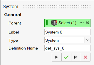
- Optional: To select a Parent system, click the Advanced selector ….
- Optional: Edit the Label.
- Optional: Edit the Definition Name.
-
Click Apply
 .
A system is added to the model by creating a definition and instantiating it. It is now available for editing.
.
A system is added to the model by creating a definition and instantiating it. It is now available for editing. - Right-click and mouse through the check mark to exit, or double-right-click.
Edit a System
Edit an analyst system using the Systems tool or Property Editor.
- In the Model Browser, select the system.
-
Choose from the following methods:
Table 1. To use this method Do this Systems tool - On the Motion ribbon, under Profile, select
Analyst.
- Under Create, select the Systems tool.
- The guide panel is displayed.
Property Editor - From the View menu, select Property Editor.
- On the Motion ribbon, under Profile, select
Analyst.
- In the guide panel, under Attachments, add/modify/delete an attachment. For more information, see Attachments.
System Properties
Descriptions of system properties in the Property Editor.
| Property Name | Description |
|---|---|
| General | |
| Name | The entity's name |
| Variable Name | The variable name, a unique identifier string of the entity |
| ID | A unique identifying integer |
| Definition | |
| Name | Variable name of the definition that the system is an instance of |
| File | Definition file name (.mdl), if the definition is included in a file |
| File Modified | Indicates that the definition file has been modified, but not saved |
| Linked | Indicates that the definition is shared with another instance |
| PropertiesLists the properties or data members | |
| Data Members | Add/delete or modify values of properties, which can be of the
following data types:
|
| Compliant | Toggle the compliance state of the joints within the system (affects child systems too). |
| Attachments | Lists the attachments to the system. Click on the field value of an attachment, if any, to bring up the guide panel. Refer to Attachment to modify the attachment. |
| Initial Conditions | |
| Translational Velocity | |
| Vx, Vy, Vz | Toggle and set values for translational velocities in the x, y, and z directions for the system. The initial conditions are imposed on the parts within the system. |
| Rotational Velocity | |
| Wx, Wy, Wz | Toggle and set values for rotational velocities about the x, y, and z directions for the system. The initial conditions are imposed on the parts within the system. |
Note:
- Properties on the system can be linked to another entity property of the same data type.
- The Compliant option is applied to all subsystems beneath the current system.
- The Compliant option can be overridden for individual joints in the Property Editor.
- The initial condition applied on a part directly overrides the initial condition specified on the system.