Link regions and components: solid conductor
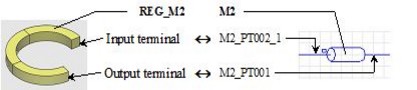
Solid conductor …
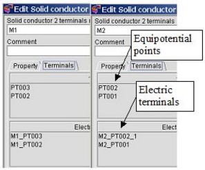
With regard to solid conductors, the user must carry out for each component the following operation:
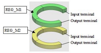
- he defines a geometric terminal for each electric terminal of the M2 component (M2_PT002_1, M2_PT001)
Define geometric terminals
To define the geometric terminals (associated with the imported electric terminals) of the regions of solid conductor type follow the next procedure:
| Step | Action | |
|---|---|---|
| 1 |
In the Physics menu:
|
|
| 2 |
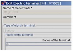
In the dialogue box Assign terminals …:
|
|
| If external terminals | If internal terminal | |
| select faces corresponding to the M2_PT002_1 terminal | select faces corresponding to the M2_PT002_1 / M2_PT001 double terminal | |
| select faces corresponding to the M2_PT001 terminal | select the orientation line | |
| → | Realization of the electric terminal / geometric terminal link. | |
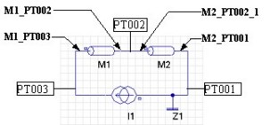
Check the links
To check the links between the electric and geometric terminals follow the next instructions:
| Edit the components … | to locate the components in the circuit |
|---|---|
|
|
| Edit the electric terminals … | to identify the geometric terminals |
|---|---|
|
|