Apply Pressures
Create pressure loads on elements by applying a load, representing pressures, to a 1D or 2D element, or to the face/edge of a solid element.
For most solvers, the pressure load is considered as force/area, therefore the magnitude of the pressure is multiplied by the calculated area of the elements to which it is applied and resolved as concentrated force loads at the associated nodes.
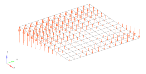
Pressures are load config 4 and are displayed as a vector with the letter P at the tail end.
You can specify the pressure's footprint by selecting the elements it affects, as well as its direction, magnitude, and the size in which its visual indicators are drawn. You can also apply the pressure to the faces of solid elements, or to the edges of plate elements.
For plate elements, the pressure is applied along the positive element normal. The Normals tool should be used first to obtain the correct orientation. The nodes on face option is not necessary if applying the pressure to the face of a plate element. If applying the pressure to the edge of plate elements, the nodes on edge option is required to define which of the three or four edges of the plate element you wish to apply the pressure to. For solid elements, the nodes on face option is required to define which of the faces you wish to apply the pressure to.
-
From the Analyze ribbon, Loads tool group, click the
Pressures tool.
図 1. 
-
Select the keyword to create from the Load Type menu.
The available types depend on the current solver interface.
- If applicable, set the entity type to Elements or Sets.
- Select elements (1D, 2D, 3D) or sets to which pressures will be applied.
-
Specify the magnitude and direction of the pressure.
- Constant Components
- Specify the direction and magnitude of the load by entering the X, Y, and Z values of the components.
- Constant Vector
- Specify the magnitude, then use the plane and vector tool to specify the vector along which the load should act.
- Curve Components
- Specify the X, Y, and Z components to define the direction and magnitude, for example, (2,2,2) will be twice the magnitude of (1,1,1). Next, select an existing curve. Last, specify a factor for the curve’s xscale to use the same curve for many different cases, but vary the scale of its intensity or time to match the needs of your current load.
- Curve Vector
- When working with loads that are time dependent, use this method to first specify a magnitude (yscale) for the curve. Next, select an existing curve, then use the plane and vector tool to specify a direction, if necessary. Last, specify a factor for the curve's xscale to use the same curve for many different cases, but vary the scale of its intensity or time to match the needs of your current moment.
- Equation
- Specify the loading equation. Use the plane and vector tool to specify a direction, then select the coordinate system to which the vector corresponds.
- Field Loads
- Interpolate and extrapolate loads from existing loads. You can then select the desired elements to which you wish to add loads, and any existing loads on which you wish to base additional forces.
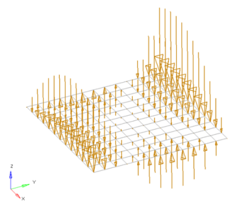
- Linear Interpolation
- Interpolate loads from a saved file or existing loads.注: Only available for shell elements.
- You can then select the desired nodes to which you wish to add
loads, and pick three or more existing loads that enclose those
nodes. When you interpolate, a linear function is used to create
additional loads on the selected nodes, with magnitudes based on the
magnitudes of the loads that you had selected.
図 2. 
- If working in a controller, click Create.
Equationの指定によって、集中荷重、モーメント、荷重、温度、流束などを、適用するエンティティの座標値によって変化する荷重量を定義できます。このような荷重の例としては、適用点からの距離によって変化する温度の適用や内部の流体の高さによって変わるコンテナの壁にかかる圧力などが考えられます。