Generate Contacts Automatically
Use the Auto Contacts tool to determine contact interfaces between selections of components or elements. Based on the user-specified options like proximity tolerance, surface creation method, main surface type, and secondary type, the tool generates contacts based on set segments or node and element combinations.
Restriction: This workflow is only available in the
OptiStruct profile.
-
From the Model ribbon, Contacts tool group, click the
Auto Contacts tool.
Figure 1. 
-
On the guide bar, click
 to set contact calculation options for Sliding and Tied contacts.
Some of the main parameters include:
to set contact calculation options for Sliding and Tied contacts.
Some of the main parameters include:- The maximum feature angle used to identify contacts
- The contact surf (set) types - main and secondary
- Main - Surface (elems) or Segment (Set Segment)
- Secondary - Node, Surface (elems), or Segment (Set Segment)
- The method for creating main and secondary surfaces
- The property to attach to the contact pairs
- Select the contact type that gets generated from the guide bar drop-down.
- If using a proximity tolerance to determine the distance between selections, enter a value.
-
Select the components or elements to create contact interfaces between.
Figure 2. 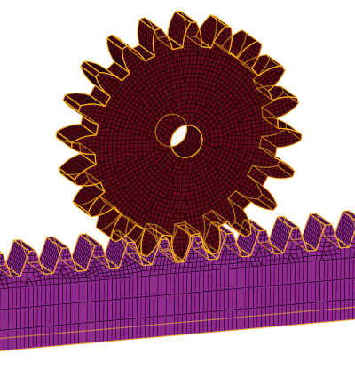
- Optional: If the Property Options setting is set to Use existing property, you can select and assign a PCONT property.
-
Click Find.
The evaluation is executed. If valid contacts are found, a model tour style guide bar appears that you can use to review the various node, surface, or segment creations.
-
Review the next or previous contact by clicking
 or
or
 on the guide bar.
Figure 3. 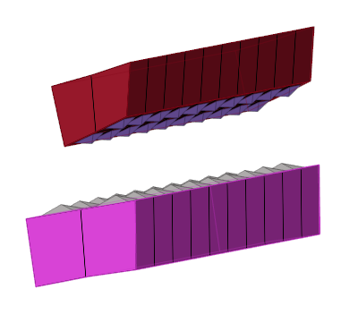
- Optional:
Use the options on the display toolbar to toggle the visibility of associated
components and main/secondary interfaces as well as adjust the transparency
level.
Figure 4. 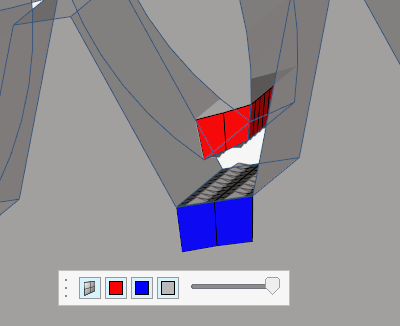
- Optional:
Edit the content of the Secondary and Main selectors (node, surface, or segment
selections) to correct and/or improve the contact generated by the tool.
Note: The entity selectors on the model tour guide bar are restricted by the main and secondary types defined in the options menu. If set to Node, only nodes are available for selection. If set to Surfaces, you can only select elements. If set to Segments, you can only select faces/edges.
- Optional: Use the checkbox beneath the guide bar to swap the main and secondary interfaces.
-
Click one of the action buttons on the guide bar.
 - Reject individual contacts
 - Reject all contacts and return to the Create
context
- Reject all contacts and return to the Create
context - Accept contacts and exit the tool
Generate Contacts Automatically in the Abaqus Interface
Use the Auto Contact tool to identify and create contacts.
Restriction: This workflow of the Auto Contact tool is only available in the
Abaqus profile.
The Auto Contact tool uses the following logic to identify and create contacts:
- The surface of the component or an element set defined as rigid body and the surface defined as rigid surface will always be a main surface.
- The surface of a component or an element set with coarser mesh will be a main surface.
- The surface of a component or an element with less stiffness (uses young’s modulus of the material) in comparison with the mating surface will be a secondary surface.
- The larger surface will be identified as a main surface.
-
From the Model ribbon, Contacts tool group, click the
Auto Contacts tool.
Figure 5.
The Auto Contact dialog opens. -
Define contact options.
- Application region
- Select the components or elements to detect contact.
- Contact tolerance type
- Use proximity tolerance or shell thickness from the property.
- Proximity tolerance
- A real value.
- Feature angle
- A value to determine the extent of curvature required to identify contact surface.
- Surface creation method
-
- Consolidate
- Create a single contact pair involving multiple pairs of main and secondary surfaces.
- Do no consolidate
- Create an individual contact pair for each pair of main and secondary surfaces.
- Extend surface to feature
- Create larger main and secondary surfaces that may extend to feature edges based on the angle of preference.
- Add layers to extend main surfaces
- Extends the main surface by layers of elements based on the options
chosen.Restriction: This option is only available for Consolidate and Do not consolidate surface creation methods.
- Feature angle for layers
- The allowable angle for the layer extension on the main surface.
- Contact type
- Select Contact or Tie.
- Secondary type
- Define the secondary surface as element based or node based.
- Contact surface name prefix
- Your preferred prefix for the name of the main and secondary surface.
- Define main and secondary with components
- Define the main and secondary surface using the entire component.
- Property option
- Generate a new contact property or use an existing one.
- Property options to generate
- Select an existing card or specify the card that needs to be created.
- Create contact/tie in confirmed state
- Create the contact without reviewing.
- Run penetration check before contact creation
- Check for any mesh interferences.
- Consider contact within a component
- Select a single component and detect contact between disjointed elements within the component.
- Click Create.