Selections work after you have configured the Display Selections.
To add a Setup Selections sub-section:
Right-click Setup Selections or click the icon to add selections of the following
types:
Icon
Description
Adds a manual selection to the analysis
Adds a Grid bin
Adds a Geometry Bin
Adds an imported Geometry Bin Group
Right-click a specific selection from the Analyst Tree and select any of the
following:
Icon
Description
Renames the Selection group
Copies the Selection group
Deletes the Selection group
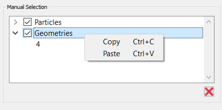
Add a Manual Selection
Manual selection allows you to and track individual particles, Contacts, or
Geometries. You can then display, color, graph or export data based on these selections. You
can also define and add queries, as well as display detail in the data browser.
To add a manual selection:
Select Setup Selections, right-click and then select
Add Selection, and then select Manual
Selection.
Select the Enable Manual Selection checkbox.
The cursor changes to a cross hair.
Move the pointer into the Viewer.
Click your selection, or press and hold the mouse button and then drag the
pointer to draw a selection box.
All particle and Geometry elements captured by the box that match the
current filter will be part of the selection.
If an element is not displayed in the Viewer, it will not be captured by
the Selection box. By default, all selected elements are highlighted in
orange.
You can draw additional selection boxes to add further elements to the
selection.
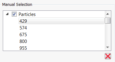
All captured elements are listed by their ID in the Manual Selection
area.
Click the
icon to completely remove elements from the selection.
Note: If you know the specific ID, you can paste the ID
into the Geometry of particle sections of the Manual Selection box.
Clear the Enable Manual Selection once complete.
Select the Display in Data Browser checkbox.
You can add information about the elements in the Selection section within the
Data Browser.
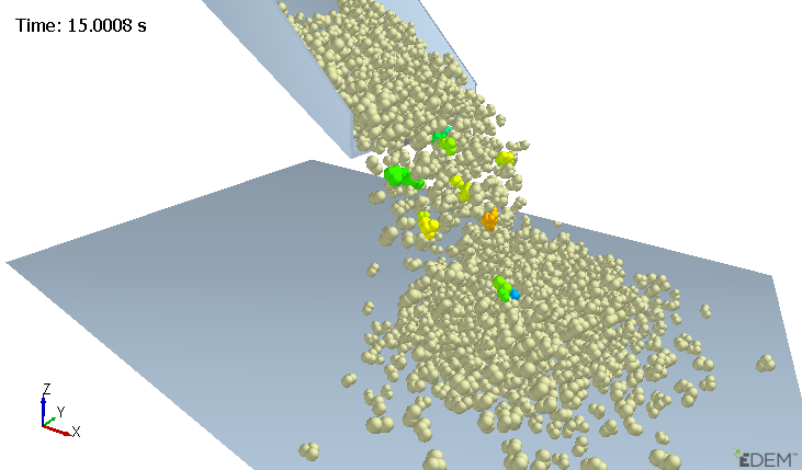
The following example shows a Selection Group where several particles have
been individually selected. Coloring has been applied to show Velocity.
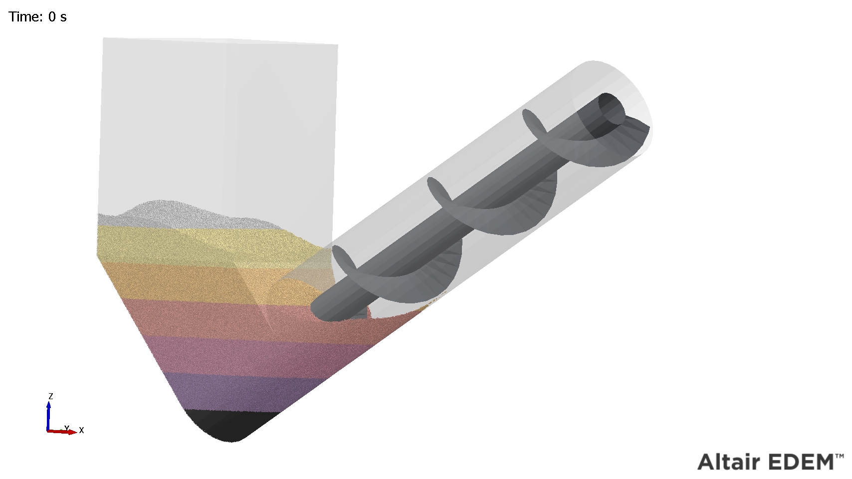
The following example shows where the material has been selected in the
form of bands, with each band colored differently to show the cut-depth of
the material.
Add a Grid Bin Group Selection
A Grid Bin group splits the model domain into a lattice. Each grid is known as a bin
group and each cell is known as a bin. You can monitor anything inside or moving through
each bin.
To add a Grid Bin group:
From the Setup Selections Section, right-click and select Add
Selection and then select Grid Bin Group.
Define the selection and then click Apply to apply the
settings and display the group in the Viewer.
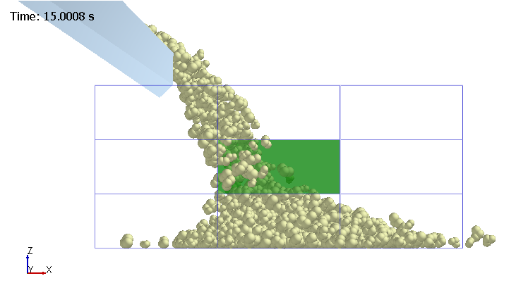
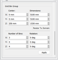
The following example shows a Grid Bin Group with a highlighted bin at the
center. By default, the bin group covers the entire domain. However, it can be
limited to a specific area by defining a box using the center point and box
dimensions options:
The number of bins in the group is determined by the number of bins
along each axis.
The orientation of the grid bins can be altered using
the rotation option.
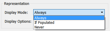
Empty bins (those containing no elements) can also be removed using the
Display Mode dropdown list.
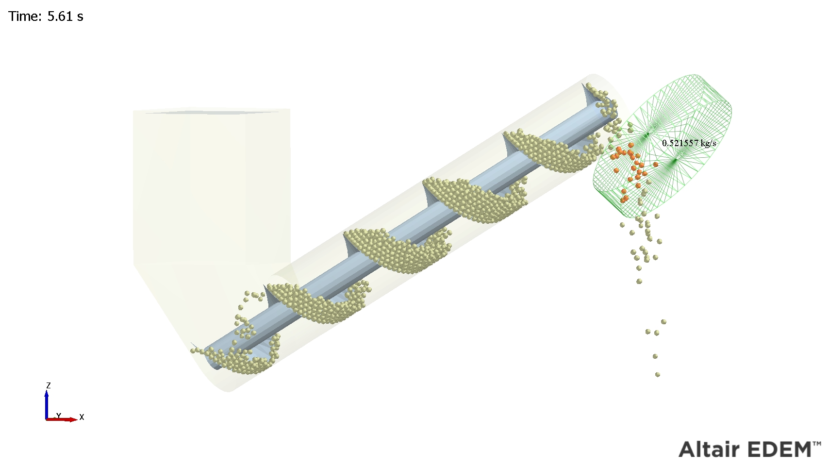
Add a Geometry Bin Selection
A Geometry bin is a bin element based on a Box or Cylinder Geometry type. You can
link its position to any static or dynamic Geometry section. The bin is displayed as a mesh
of blue lines.
To add a Geometry bin selection:
From the Analyst Tree, right-click Setup Selections
section and click Add Selection.
Select Geometry Bin.
Select the Geometry type: Box or
Cylinder.
Set the bin’s properties to define its size, shape, and initial position.
Set the filter options to select what to include in the bin.
By default all particles are included.
Select the display mode and on-screen query options.
For example, set the display mode so that the bin is displayed only when it
contains particles.
Select whether to link the bin’s position to a Geometry element defined in the
Creator.
This links to the center (or zero-point) of the Geometry. If the Geometry has
dynamics, the bin will move along with it.
The following example shows a Geometry bin based on a cylinder. The bin
indicates the mass flow rate and moves with the Geometry section it is linked
with.
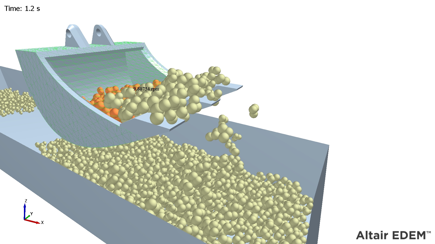
Add an Imported Geometry Bin Group
The imported Geometry Bin group allows you to define a bin group based on an imported
mesh file or CAD template created in another package. You can then link the bin group’s
position to any defined geometry.
To add an imported Geometry Bin Group:
From the Analyst Tree, right-click Setup Selections and
click Add Selection.
Select the imported Geometry Bin Group.
In the CAD Template Selection section, click
Import and then navigate to a CAD template file.
When prompted, set the units and select Merge Sections
to set the template as one bin, or leave it unselected to create one bin for
each Geometry element. The imported file must contain only solid Geometry
elements as you cannot import surfaces (non-closed elements such as a
plane).
Set the filter options to determine what to include in the bin.
By default all particles are included.
Select the display mode and on-screen query options.
For example, set the display mode so that the bin is displayed only when it
contains particles.
Select whether to link the bin’s position to a Geometry element defined in the
Creator.
If the Geometry is dynamic, the bin will move along with it. The following
example shows an imported Geometry bin linked to a moving bucket Geometry. A
query has been added to display the average particle angular velocity.
 icon to add selections of the following
types:
icon to add selections of the following
types:


 icon to completely remove elements from the selection.