Create a Folding Table
Use the Create Table tool to create a table on which the airbag will be folded.
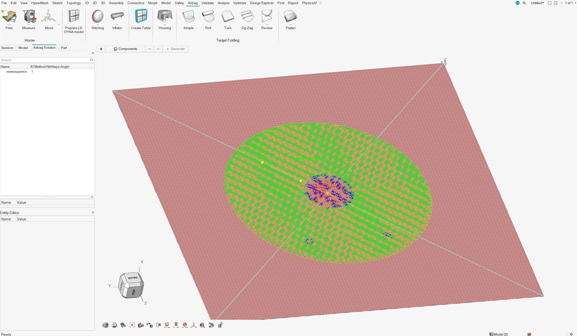
This is a shell part that will be rigid. The dimensions are computed from the size of the airbag, and the elements are regularly and equally spread. The meshing line can then be used as an indicator of the positions.
You should start with an airbag model with properties, materials and contacts.
-
From the Airbag ribbon, click the
Create Table tool.
Figure 1. 
-
On the guide bar, click
 to define
folding options.
to define
folding options.
- Folds Directory: Defines where the files will be saved. This directory will be used for every fold.
- Gap: Defines the gap between the airbag and the table.
- On the guide bar, click Components.
-
Select the airbag components.
A microdialog opens.
-
Make your selections in the microdialog.
Option Description Method Define the normal direction to the table. Options include Normal Axis or 3 Nodes. Reference Node Select one node on the airbag. Global Axis Select from X, Y, or Z. X Axis Available for the 3 Nodes method only. Defines the X axis by the reference node and the X Axis node selected.
XY Plane Available for the 3 Nodes method only. Defines the XY plane based on the third node selected and the two previous nodes.
Preview Table Click Preview Table to display the Table component. Flip Table Click Flip Table to reverse the table location to the other side of the airbag. -
Set advanced selections as necessary by clicking
 on the guide bar.
- On the guide bar, click Generate.
- After the table is created, the Airbag Solution Browser is displayed, which displays each fold created.
- Define the folds that must be simulated.
-
Upon completion, right-click in the Airbag Solution Browser
and select Realize the sequence to generate a Radioss deck.
Running this deck simulates the full folding sequence.
Figure 2.