Configuration File
The configuration file (feconfig.cfg) is used to define the structure of the realization.
Element Structure
Weld definitions are solver dependant (OptiStruct, Radioss, and so on). The specific solver template for the type of weld must be loaded before the welds can be created using a connector entity.
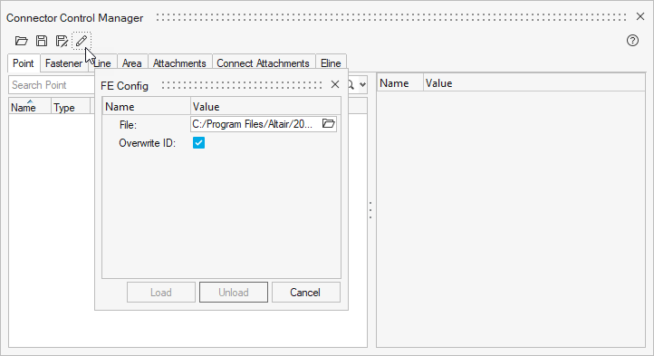
The configuration file can be manually loaded via the Control Manager.
The configuration file can be automatically loaded when HyperMesh launches. When launched, HyperMesh searches for the feconfig.cfg
file in the following locations. The locations below are listed in search order.
- <install_directory>/hwdesktop/hw/bin/win64
- HW_CONFIG_PATH (a specified environment variable)
- Your home directory (for example, in UNIX)
- The current working directory
Weld Definition Template
All the configurations follow the same template.
Each * flag is explained in detail below.
CFG <SOLVER> <USER_FE_TYPE> <USER_FE_NAME>
*filter <CE_TYPE>
*style <STYLE_TYPE> <STYLE_NUM>
*head
<HM_FE_CONFIG> <HM_FE_TYPE> <RIGID_FLAG> [<DOFS>]
*bodyext <BODY_FLAG>
<HM_FE_CONFIG> <HM_FE_TYPE> <RIGID_FLAG> [<DOFS>]
*body <BODY_FLAG>
<HM_FE_CONFIG> <HM_FE_TYPE> <LENGTH_LOCATION_FLAG> [<DOFS>]
[<HM_FE_CONFIG> <HM_FE_TYPE> <LENGTH_LOCATION_FLAG> [<DOFS>]]
*post <POST_SCRIPT_NAME>
*calcmethod <CALCULATION_METHOD>
CFG <SOLVER> <USER_FE_TYPE> <USER_FE_NAME>-
SOLVER- The solver template for which FE needs to be created. Supported solvers are: Abaqus, ANSYS, LS-DYNA, Nastran, OptiStruct, or PAM-CRASH.
USER_FE_TYPE- A unique (with respect to a solver) user-defined configuration
type ID. User-defined
CFGs should use numbers greater than 10,000 to ensure no collisions with future native HyperMeshCFGs. USER_FE_NAME- The user-specified name for the FE configuration. The specified name is saved and displayed in the Connector Browser.
*filter <CE_TYPE>*filter <CE_TYPE>can be used to allow only the specified connector types to realize the configuration.CE_TYPEspot= Point toolbolt= Fastener toolseam= Line toolarea= Area tool
Figure 2. 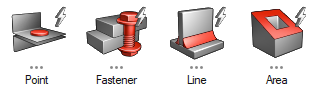
*style <STYLE_TYPE> <STYLE_NUM>- The
*styleoption indicates that the configurations have specific behaviours associated during realization, and that they are native types. - The style and style number affect the attributes shown in the control. In
the example in Figure 3,
the only difference is the style, but the control attributes are very
different.
Figure 3. 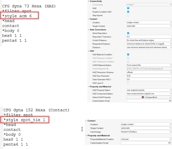
*head- The
headstring is required to specify that a rigid, 1D, or contact is to be created to connect the weld node to the surrounding shell element. *headlines must be followed with at most oneHM_FE_CONFIGline.Figure 4. 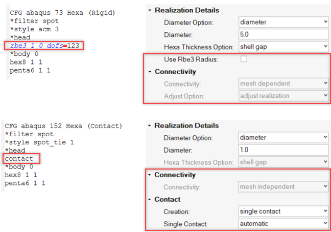
*bodyext- The
bodyextstring is required to specify that the body of a weld has an extension associated with it. Currently, this extension can be created by a group of weld elements protruding at a distance of 0.5*times the thickness of the connected shell elements.*bodyextlines may be followed by one or moreHM_FE_CONFIGlines. - Currently, it is used for the Hilock realization, but it can also be used
with other realizations if you want the body element to have extra
protrusion.
Figure 5. 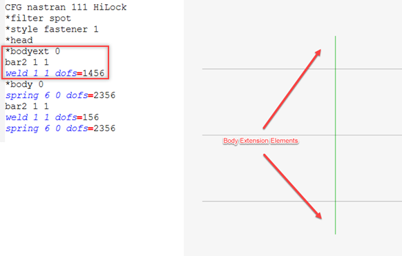
*body- The
*bodystring is required. - How the defined body elements are used is controlled by the
*style.Figure 6. 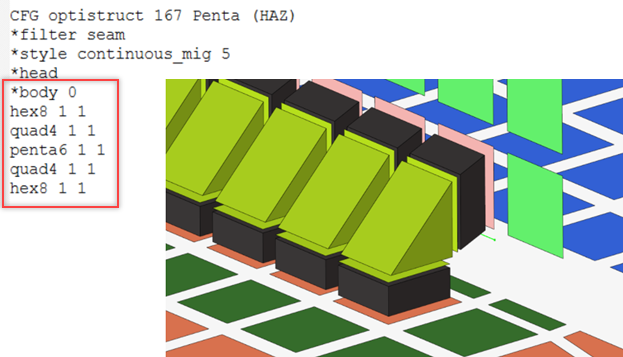
*post- The lines are optional, but if specified it must be followed by the name
(excluding path) of a valid TCL script with a .tcl extension. This TCL script must
be located in, and will be searched in, the following order:
- Current working directory
- Your home directory
- Paths in
HW_CONFIG_PATHenvironment variable - Installation directory
- hm/bin directory
- hm/scripts directory
- hm/scripts/connectors/ directory
*calcmethod- The
*calcmethodtag can be used to define any valid custom realization (points/fasteners) to have a calculation method. - Currently this is only supported for Huth and Rutman.
Figure 7. 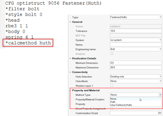
FE Specification Rules
- Each solver will have a specific definition so the same user-defined types can be repeated for each solver.
- 1D and 3D element combinations are not supported.
- The total length of series welds cannot exceed 1.0 (100%). Hence, there cannot be three welds specified in a series with a length factor of 0.5 (50%) each.
- Series and parallel weld element combinations are not supported. Series welds are not supported where the link entities are coincident.
- Series welds are not created when the distance between the connecting link entities is zero.
- Your comments should start with a hash character: #.