From the menu bar, click File > Open > HyperMesh Model.
Browse to your working directory, select frame.hm, and
click Open.
If prompted, click Change to change the solver
interface to OptiStruct while opening the
model.
A finite element model appears in the modeling window.Figure 1.
Review the Subsystem Configurations
In this step, you will review the preexisting subsystem configurations already in the
model.
From the Assembly ribbon, click the Subsystems
tool.
Figure 2.
The Subsystem Browser opens.
In the Subsystem Browser, click the view icon and set it to
.
This view shows the Subsystem Configuration view.
In the top-left portion of the Subsystem Configuration view, click back and
forth from one active subsystem configuration to the other.
Each time a subsystem configuration is made active, click Yes when prompted to
realize connectors.Figure 3. Observe that when a subsystem configuration is made active, the model is
updated accordingly.Figure 4.
Make Subsystem Configuration 1 Active, and close the Subsystem Browser.
Create an Exploration
From the Design Explorer ribbon, Exploration tool group, click the
Create Explorations tool.
Figure 5.
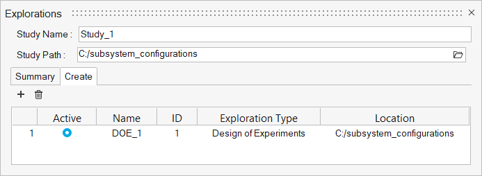
The Explorations dialog opens.
Click and
select DOE.
In the Study Path field, browse to and select the folder to store your
exploration files.
Figure 6.
Close the Explorations dialog.
From the Exploration tool group, click the Design
Explorer tool.
Figure 7.
The Design Explorer Browser opens. You can see the newly created
exploration. Additional exploration entities will appear here as
well.
Create the Exploration Inputs
From the Design Explorer ribbon, click the Configuration
tool.
Figure 8.
The Subsystem Configuration DV dialog
opens.
In the Subsystem Configuration DV dialog, select both
subsystem configurations.
Figure 9.
Click Create.
One configuration design variable is created.Figure 10.
Create the Exploration Responses
From the Design Explorer ribbon, click the Mass/Volume
tool.
Figure 11.
On the guide bar, click .
A mass response is created.
On the guide bar, click .
Click the Disps. tool.
Figure 12.
On the guide bar, click to open the Advanced Selection
dialog.
In the Advanced Selection dialog, complete the following
steps.
Set the selection drop-down to By ID.
Enter 220903.
Click OK.
A displacement response is created.
On the guide bar, click .
The DOE now consists of one design variable and two response variables.
Figure 13.
Evaluate the Exploration
From the Design Exploration ribbon, Evaluate tool group, click the
Evaluate tool.
Figure 14.
The Evaluate dialog opens.
Optional: Increase the number of concurrent runs by increasing the Multi Execution
number.
Click Run.
The DOE is evaluated. In this case, there will be a nominal run plus 10
optimization runs.
This may take a few minutes depending on your
computer.
When the evaluation is complete, the Evaluation
Status dialog should look like Figure 15.Figure 15.
Close the Evaluation Status dialog.
Review the Evaluation
From the Design Exploration ribbon, Evaluate tool group, click the
Results Explorer tool.
Figure 16.
The Results Explorer opens.
Review the Summary table, which shows the input, objective, and constraint
values for each run of the optimization.
Figure 17.
Try loading the results for runs one and two to visualize and compare the
results.
Right-click on run 1 and run 2, and select Apply variables to
model.
Click Yes when prompted.
The subsystem configuration used by the selected run is loaded. If additional
design variables had been used, such as part thicknesses, they would also be
applied to the model.
Figure 18 shows subsystem configuration 2 from run 2 applied.


 and set it to
 .
This view shows the Subsystem Configuration view.
.
This view shows the Subsystem Configuration view.


 and
select DOE.
and
select DOE.


 .
A mass response is created.
.
A mass response is created. .
.

 to open the Advanced Selection
dialog.
to open the Advanced Selection
dialog.


