
PBEND
Bulk Data Entry Defines the property of curved beam or pipe elements defined via the CBEND entry.
Format
| (1) | (2) | (3) | (4) | (5) | (6) | (7) | (8) | (9) | (10) |
|---|---|---|---|---|---|---|---|---|---|
| PBEND | PID | MID | FSI | RM | T | P | RB | THETAB | |
| NSM |
Example
| (1) | (2) | (3) | (4) | (5) | (6) | (7) | (8) | (9) | (10) |
|---|---|---|---|---|---|---|---|---|---|
| PBEND | 1 | 2 | 1 | 0.85 | 0.025 | 50 | 6.0 |
Definitions
| Field | Contents | SI Unit Example |
|---|---|---|
| PID | Unique bend property
identification.
Default = EID (Integer > 0 or <String>) |
|
| MID | Material
identification. 1
|
|
| FSI | Flexibility and stress
intensification factors flag. 3 (1≤ Integer ≤ 4) |
|
| RM | Mean radius of the
pipe cross-section. Figure 1
(Real > 0.0) |
|
| T | Thickness of the wall
of the curved pipe. Figure 1 (Real ≥ 0.0; RM + T/2 < RB) |
|
| P | Internal pressure.
(Real or Blank) |
|
| RB | Radius of the arc of
the CBEND element. Required only for GEOM = 3 on CBEND. (Real) |
|
| THETAB | Angle of the arc of
the CBEND element. Required only for GEOM = 4 on CBEND. (Real, in degrees) |
|
| NSM | Nonstructural mass per
unit length. Default = 0.0 (Real) |
Comments
- For structural problems, MID may reference only a MAT1 material entry. Only structural problems are currently supported. Heat transfer analysis is not supported for the CBEND/PBEND entries.
- String-based labels allow for easier visual identification of properties, including when being referenced by other cards (for example, the PID field of elements). For more details, refer to String Label Based Input File in the Bulk Data Input File topic.
- For this Curved Pipe format, the
FSI option defines the in-plane flexibility factor
(K_z), the out-of-plane flexibility factor (K_y), the in-plane stress
intensification factor (S_z), and the out-of-plane stress intensification
factor (S_y). K_z and K_y must not be less than 1.0. Accordingly, OptiStruct sets their values to 1.0, when required.
The available options are:
- FSI = 1
In-plane Flexibility Out-of-plane Flexibility In-plane Stress Out-of-plane Stress Where,
is the radial offset of the neutral axis due to bending of the curved beam (Boresi, Arthur P., and Richard J. Schmidt. Advanced mechanics of materials. John Wiley & Sons, 2002.)Figure 1. CBEND Element Coordinate System for Pipe Bend Format 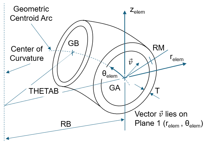
- FSI = 2 (ASME code Section III,
NB-3687.2, NB-3685.2., 1977)Where,
In-plane Flexibility Out-of-plane Flexibility In-plane Stress Out-of-plane Stress With corresponding to the default stress recovery points, Di, Ci, Fi, Ei, respectively (Figure 1).Note: The above equations are only valid for , as per NB-3685.1. For , , a warning is issued but the solution sequence is not interrupted. - FSI = 3 (Research Council
Bulletin 179, Dodge and Moore)
In-plane Flexibility Out-of-plane Flexibility In-plane Stress Out-of-plane Stress Where and are defined as in FSI = 2.
- FSI = 4 (ASME code N-319-3
(approval date of January 17, 2000))
In-plane Flexibility THETAB = 0°:
THETAB = 45°:
THETAB = 90°:
THETAB ≥ 180°:
Where,
For any values 0° < THETAB < 180°, is linearly interpolated with THETAB. The resulting must not be less than 1.0.
Out-of-plane Flexibility In-plane Stress THETAB = 0°:
THETAB = 45°:
THETAB ≥ 90°:
For any values 0° < THETAB < 90° , is linearly interpolated with THETAB. The resulting must not be less than 1.0 or the interpolated value for THETAB = 30° . OptiStruct modifies the value of accordingly.
Out-of-plane Stress The resulting must not be less than 1.0. OptiStruct modifies the value of accordingly.
- FSI = 1
- The stress intensification factors,
which determine the stresses at the two endpoints of the
CBEND elements, are by default at the stress recovery
points Ci, Di, Ei, Fi (i = 1,2 corresponding to grid points A and B) of the
cross section (Figure 2).
Figure 2. Default Stress Recovery Points at Cross Section of CBEND Element 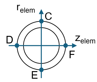
- For this curved pipe format of the
PBEND card, the shear effects in the stiffness matrix
are considered via the following shear correction factor:
Where, .